Compressor solves solution gas bottleneck
Ken J. VargasFalcon EDF Ltd.CalgaryFrank Lowe
Gulf Canada Resources Ltd.Calgary
A new turbine-driven, centrifugal compressor installation increased gas handling capacity in the Westerose D-3 oil reservoir, about 100 km south of Edmonton.
Gulf Canada Resources Ltd.'s Westerose D-3 oil reservoir has prolifically produced oil for the last 3 decades. Produced gas has been reinjected into the gas cap to maintain heterogeneity and reservoir fluid interfaces.
The oil pay, once several tens of meters thick, is now only several meters thick. As a consequence, horizontal wells have been drilled to recover incremental oil and accelerate depletion.
As oil production continues, increased quantities of solution gas must be handled by the Westerose facility (Fig. 1 [112657 bytes]). All produced gas is reinjected into the reservoir after processing.
The cost-effective design of the new compressor installation was based on Gulf's aggressive drilling program for recovering oil as quickly and economically as possible to reach full blowdown.
An additional 18 MMscfd of gas handling was required. The Westerose battery pressure is 130 psig and reinjection pressure is 1,450 psig.
After evaluating several alternatives, Gulf determined that the most cost-effective alternative was a turbine driver, tandem compressor (centrifugal, multistage). The driver required 4,000 hp. The advantage of this solution is that once the oil is depleted, the compressor is easily reconditioned for gas cap production.
Gas cap production sales pressure is from 450 to 1,400 psig. Hence, one tandem barrel (second stage) can be run as configured. The first barrel is then restaged to mirror the second-stage barrel. Thus, both barrels can run in parallel to compress 36-40 MMscfd of gas-cap gas.
The advantage of the turbine driver, two-stage centrifugal unit compared to a reciprocating compressor is obvious when one compares cost and delivery. A 4,000 hp reciprocating compressor costs $US5.3 million installed, whereas, the reconditioned Westerose centrifugal unit cost only $3.7 million.
Time from authority for expenditure to commissioning took only 5 months.
Design considerations
The main design considerations included:
- Performance of a field battery study to determine potential bottlenecks for increased oil production and future D-3 pool gas-cap blowdown
- Completion of the compression project design basis, location, and interconnection at the battery such as available utilities
- Preparation of AFE, cost, schedule, and economic evaluation of the project (order compressor)
- Development of the project flow diagram (PFD), and material and energy balance (Fig. 2 [102150 bytes])
- Ordering of all long delivery items and equipment
- Preparation of process and instrumentation drawings (P&IDs)
- Preparation of project piping isometric drawings, equipment layout, and civil/foundations drawings (from P&IDs and vendor equipment drawings, if available)
- Ordering of (based on the drawings) all project consumable materials such as piping, valves, fittings, rebar concrete, etc.
- Awarding of construction contracts for civil, mechanical, electrical, and instrumentation.
It is important to emphasize that speed of execution and extensive design and project engineering experience were required to conclude this project quickly. Frequent, scheduled and unscheduled, communications sessions with construction and plant operations personnel maintained the project on track.
An open and frequent channel of communication with operations and construction personnel is essential to ensure that equipment is compatible and all design expectations are met.
Battery design
The Westerose D-3 battery has undergone many design changes during its operation. Separators, flow lines, compression, dehydration, and other facilities have been added without an overall production strategy. This unplanned expansion occurred because changes in the field characteristics were too fast and manpower shortages prevented detailed planning.
To avoid adding facilities, without looking at the battery's maximum capabilities and bottlenecks, Gulf commissioned a detailed engineering study to evaluate the present-vs.-maximum capacities for the complete plant facilities. The battery was broken down into modular blocks as follows:
- Gathering lines-The group and test lines had some capacity available. The existing manifold was a bottleneck. Two-phase gas/liquid flow should be avoided, because the gas phase backs up oil flow. Hence, the gathering lines needed to be at as high a pressure as possible. A simulation, with well test and field pressure data, of all gathering lines revealed that an extra 700 bbl could be handled by the gathering lines.
- Group/test separators-Capacities of the four test separators are maximum gas 51 MMscfd, existing gas 2 MMscfd, maximum oil 2,705 b/d, and existing oil 220 b/d. Capacities of the two group separators are maximum gas 41 MMscfd, existing gas 21 MMscfd, maximum oil 2,139 b/d, and existing oil 1,981 b/d.
Because of testing requirements and manifold configuration, the test separators cannot be used as group separators.
- Treaters-Two heaters are available at the battery to lower bs&w of the oil to less than 0.5%. The total treating capacity for both treaters is 31,450 b/d.
- Compressors-Seven reciprocating compressors provided solution-gas compression at the time of the study. The available solution-gas compression was 6,850 hp, with only 6,300 hp being utilized. To tap into this additional 500 hp, major plant modifications and compressor recylindering would be required.
One additional reciprocating compressor at the battery is for gas reinjection and gas lift.
- Water injection-Water reinjection was not identified as a bottleneck. A prolific water reinjection well can reinject in excess of the current rates of 3,100 b/d at vacuum wellhead pressure.
- Dehydration-The solution gas is shipped via pipeline to Gulf's Rimbey gas plant. The plant sweetens the gas and removes liquids. After processing, the gas returns via pipeline to Westerose for gas cap reinjection. The Rimbey gas plant is 15.2 miles southwest of the Westerose battery.
To avoid hydrates when shipping water-saturated solution gas to Rimbey, after compression, the gas is dehydrated at the battery. The total dehydration capacity at the battery is 70 MMscfd, well in excess of required future capacities.
- Gas reinjection-One gas reinjection compressor is available to inject solution gas back into the reservoir. This compressor is rated at 35 MMscfd at 700 psig. The new turbine-driven compressor will reinject solution gas directly into the reservoir to accelerate production.
- Westerose Rimbey pipe line-Both pipeline segments are operating at capacity, 35 MMscfd to Rimbey and 30 MMscfd of dry gas back to Westerose.
Costs
Based on Gulf's drilling and production forecast, the most feasible way to increase processing capacity at the battery was to add compression.
For gas reinjection an additional 18 MMscfd was required; hence, 110 psig suction pressure and 1,450 psig injection pressure was required. The increased gas compression enabled oil production to increase to 3,770 b/d from 3,020 b/d. Gas production increased to 59 MMcfd from 40 MMscf and water production increased to 5,330 b/d from 4,530 b/d.
The compressor selected was a refurbished turbine-driven centrifugal Solar Centaur compressor with an estimated installed cost of about $3 million.
Table 1 [47394 bytes] shows the AFE cost breakdown and actual costs. The payout period was determined to be under 1 year, considering only the incremental oil production. The incremental gas produced at blowdown improves the economics further.
Fig. 3 [170154 bytes] shows the original project schedule. In the actual schedule, because certain components of the compressor were not available, start-up was delayed until mid-March.
Process flow
The process flow diagram and material balance considered two different scenarios, one for solution gas recompression and reinjection, and the other for gas-cap blowdown.
From the PFD, all equipment, instrumentation, valves, vessels, pumps, etc. were sized. Major equipment (long delivery) could not be ordered prior to the preparation of the PFD material balance.
P&IDs
The P&IDs followed the PFD material balance drawings. The P&IDs were the first step of the detailed engineering phase.
The P&IDs and vendor drawings and specifications formed the basis for all detailed design. P&IDs and PFDs were required for all detailed design disciplines, electrical, instrumentation, piping, mechanical, and civil.
Detailed design
The detailed design provided the engineer with two key functions: a plan of how all equipment fits together and is interconnected, and a list of all materials and consumables to purchase.
The civil detailed design packages provided quantities of rebar, concrete structural steel, and the location and dimensions/special procedures for the installation. The detailed mechanical design packages (piping isometrics layouts) show how the equipment is interconnected/located, and the quantities of pipe valves, instrumentation, and fittings required to erect the compressor and ancillary equipment.
The detailed electrical design packages show the quantities of cables, conduit, junction boxes, etc. and how all electrical equipment is interconnected and installed.
Construction/contracts
To prevent holding back construction by going out for formal bids, in this case after evaluating various contractors, the construction was awarded on a unit rate bid basis.
As a precaution, one could take bids for time and materials from prequalified and tested contractors. This should include issuing the most up-to-date engineering information available, (usually P&IDs and layouts) and requesting an execution plan rough cost. This forces the contractor to think the job through, without a formal bid document, and gives the owner an idea of what can be expected during construction.
About a full month was saved on the project schedule because the contractor could start construction as soon as all detailed design was complete.
Once the detailed design was complete and construction contractors were selected, the construction commenced. One or multiple contractors could have been selected (electrical, mechanical civil), depending on the control desired during construction.
The following should be considered before embarking into a time-and-materials contract. (Note: The majority of consumables are ordered by the engineering company; the construction contractor only needs to order the top-off items.)
- To maintain project coordination and productivity, the construction effort must be closely coordinated by a company representative.
- The engineering team must provide continuous support and work closely with the contractor. Design dilemmas and issues must be dealt with quickly to maintain project momentum.
- The contractor must provide experienced and productive personnel to execute the project.
Equipment and systems
The project involved installation of a number of different systems and equipment.
Turbine/compressor package
The compressor package was the first item ordered. Because this package had the longest delivery time, when the approximate process conditions were known, new and refurbished packages were investigated.
Based on deliveries, a new package was discarded immediately (1 year). A refurbished package was ordered in mid-September for delivery at the end of January 1996. This was considered excellent turnaround for a turbine/compressor skid of this size.
The unit ordered was a Solar Centaur T4502 turbine driver coupled to a tandem two-barrel Solar C-160 compressor. This tandem unit was the critical path of the project. Hence the refurbishing shop was monitored carefully to anticipate any potential installation problems.
The most important aspect to remember when ordering the turbine/compressor package, is to specify realistic operating conditions. The best approach is to give the compressor vendor an operating conditions range. As some of the problems encountered showed, not specifying realistic operating conditions can cause major operating problems later.
For low-pressure inlet conditions, certain compressor impellers and corresponding seals are scarce. For the Gulf package, three low-pressure barrel impellers and the end bell flange were not readily available. After a worldwide search for these parts was conducted, a high pressure (900 ANSI) end bell was located; however, the impellers had to be specially manufactured and installed at the last minute.
The fuel and start gas source was dry sales gas at 750 psig. The turbine requires 2,000 scfm of start gas and 1,000 scfm of fuel gas. For the initial design, one Fisher 310 gas regulator was installed. When the unit was fired up, this regulator could not keep up with the high flow rate fluctuations of start gas and the 500 psi pressure drop.
The final start-up configuration for start gas included a Fisher 310 regulator separate from the fuel gas system that included a Fisher Big Joe 630 regulator and Fisher 310 regulator downstream to drop the pressure in two steps. This maintained the fuel gas pressure constant and well above the low-pressure shutdown set-point, during fuel gas rate sudden increases.
When the unit was started-up, a severe cold spell engulfed the area. As can be seen from the stream conditions (Fig. 2 [102150 bytes]), the predicted inlet temperature into the compressor was 65° F. This temperature was chosen because the solution gas arrives very warm at the battery, 90° F.
At the time, it appeared that the gas had to be cooled down before it reached the compressor suction. Hence, the line was left uninsulated. With an ambient temperature of -35° F., and 800 ft of exposed 10-in. pipe, the temperature at the suction dropped to 30° F. By changing the inlet temperature from 65 to 30° F., gas hydrates or surging is possible on the low-pressure barrel.
Pressure surges were noticed several times when trying to start the unit up at the low-suction temperature. Rather than expose the unit, the suction line was insulated, and the pressure surges disappeared.
The unit was initially specified with minimal controls. As commissioning unfolded, the operations personnel wanted to see more controls.
Some background on the operation is required, to explain the control philosophy. The Westerose facility is manned 7 days a week for one shift. If any of the following conditions occur, the compressor will go into a surge condition and shutdown:
- If sufficient oil production wells inadvertently shut-in on the wellhead ESDV (emergency shutdown valve), solution gas supply is reduced. Without a recirculation bypass valve, the compressor will go down on surge condition.
- If one of the three injection wells shuts-in (unplanned), the compressor discharge flow is reduced. The compressor will again go into surge and shutdown. Any surge condition of the compressor, will shut the turbine-driven compressor down, and cascade and shut the remaining compressors down, eventually shutting in the whole field.
To solve this problem, both surge control valves on each barrel would have to be balanced. The operations personnel preferred putting one bypass control valve around both barrels and running the control valve on suction or discharge pressure control (low-pressure control on suction, high-pressure control on discharge). The compressor could then handle plant upsets without going off-line.
Utility requirements
Some of the problems with utilities requirements such as fuel gas and start gas were mentioned previously. However, it should also be mentioned that an air compressor was installed to activate the compressor air inlet huff-n-puff to blow back the air filters.
An uninterruptible power source (UPS) system was installed to maintain the lubrication on the bearings and the lubrication oil cooler.
The only problems encountered in the utilities were several ground faults, from bare cables in the conduit, and collapse of the oil cooler internal baffle.
The ground faults were corrected easily; however, the oil cooler was repiped for temporary use as a one pass-vs.-two pass system. In this way, the cooler provided sufficient cooling until it could be repaired.
Gas coolers
One two-bank cooler was installed to cool the interstage and final discharge gas of the compressor. The coil was long and narrow to be skid transportable.
All louvers and recirculation vanes were designed to be manually set with temperature control, variable frequency drives (VFDs) on the fan motors. Good control could not be achieved with this configuration because the fans are placed between each cooler bank. Thus, the best way to control temperature was to put both VFDS to control the temperature of the most critical or highest duty cooler bank.
The operations personnel are still refining a control philosophy. The overriding consideration for the cooler design was cost, not operation. Hence, the consequences have to be accepted.
Suction scrubbers
Two vane scrubbers were ordered for the suction of each barrel to keep the size down. These worked relatively well. A point to remember here is that they must be filled with liquid, so that gas is dried adequately through the vanes.
Separator
An existing Gulf stock separator skid was refurbished as an inlet separator.
The major items that were added to the skid were an ESDV for inlet into the plant, H2S and fire monitors, gas meter run (senior), and lighting fixtures and conduit.
Piping/instrumentation
The installation philosophy for the compressor turbine package was to place the open compressor/turbine skid on a concrete slab in a pre-erected building. All internal instrumentation for the turbine and compressor was included in the open skid.
All recirculation valves, pressure relief valves, flow/pressure/temperature sensors/controllers were placed internally in the building. The piping, instrumentation, suction scrubbers, air compressor lube-oil cooler, huff-n-puff, silencers, and other compressor turbine equipment were installed in the periphery or in the pre-erected building.
All piping and equipment was installed prior to receiving the compressor/turbine package, as the schedule permitted.
Everything except the final tie-ins were installed prior to the arrival of the compressor turbine skid.
UPS/PLC/MMC
The control strategy for the process and compressor turbine package was to let the compressor turbine package company handle the compressor and turbine control (including surge) and the local engineering company handle the battery and plant process equipment and support systems such as the UPS and equipment breakers.
This developed into two separate programmable logic controllers (PLCs), one for the turbine/compressor programmed by the turbine packaging company. A second PLC for the plant shutdowns, inlet separator, and compressor aerial coolers control.
With good communication, the electrical interfaces were kept simple. The package control was set up as follows:
- Compressor turbine-The panel for start-up and operating set points was installed in a motor control center (MCC) room 10 m from the turbine. Hence, start-up is done remotely.
Pushing the start button activates the start-up sequence that allows gas to bypass the ESDVs, purge the headers, open and close recycle valves, and pressure up the discharge until the machine is on-line.
All conditions on the panel (except for set points and start-up) are relayed to a process-control computer in the gas plant control room.
- Inlet separator/aerial coolers, etc.-All equipment operating conditions/set points not part of the immediate compressor/turbine package are fed into the same computer used for the compressor in the gas plant control room.
Two main screens are available for process control (Intellution Software), one as discussed previously for the compressor package and one for all the other equipment such as the separator, coolers, etc. Hence, pressure, flow, and temperature control for all noncompressor equipment can be done from the control room.
Remote control stations were provided, where operations requested it. The inlet separator pressure controller was set up for local or computer control.
Construction/start-up
Construction was a major problem for this project. Timing was critical because oil was to be produced as quickly as possible for gas blowdown. Cold weather could not be allowed to stop construction. But the winter of 1995-96 was one of the coldest on record in Alberta
As it turned out, the footings and outdoor piping were installed during the coldest days.
Major problems encountered in the construction phase of this project were:
- The cold weather affected ground preparation and foundation and piping installation.
- The existing battery and plant had numerous lines and cables buried inside the perimeter. Therefore, extensive digging by means of water jetting was necessary to locate all the below-grade cables and piping. Once these were identified, the new pipeline foundations and footings could be installed with heavy excavating equipment. Because of frozen ground and limestone, conventional digging was slow.
- The compressor/turbine being refurbished in the U.S. had to have CSA (Canadian Standards Association) approval. Fortunately, the company providing the package had a CSA inspector check the package during construction and certify it before shipment.
- Coordination between U.S. and Canadian engineering was difficult because of the fast track. Many discrepancies such as wiring and utility piping had to be corrected after the compressor package arrived.
- A surplus separator (in Gulf's inventory) was refurbished to suit this application. Extensive wiring and instrumentation changes were required.
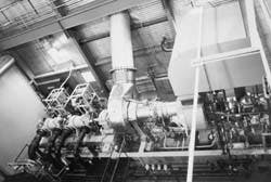
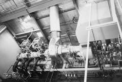
All these problems impacted costs but not significantly the schedule. Fig. 4 (below) shows the compressor as installed.
The final cost for this retroactive, fast-tracked, compressor installation was well in the range of $925/hp. As a comparison, a large reciprocating unit is in the range of $1,000-1,400/hp.
The turbine/compressor package helped debottleneck the oil production from a Westerose oil reservoir.
The Authors
Ken J. Vargas is president of Falcon EDF Ltd., an engineering consulting company in Calgary. His specialties are process and mechanical design and project management. Vargas has a BS from the U.S. Air Force Academy. He is a member of ASME and is a registered professional engineer in Canada and the U.S.
Frank M. Lowe is the district engineering coordinator-Rimbey district for Gulf Canada Resources in Calgary. He has extensive experience in work process analysis and field and plant engineering and operations. Lowe has a BS in mechanical engineering form the University of Alberta. He is a member of the Association of Professional Engineers, Geologists, and Geophysicists of Alberta.
Copyright 1996 Oil & Gas Journal. All Rights Reserved.


