'Liquid turbines' improve LNG operations
L.L. JohnsonAdding a pair of cryogenic hydraulic turbines, often called "liquid expanders," into an LNG processing train can increase plant annual revenues by 3-4%.
BW/IP International Inc.
Long Beach, Calif.Gerard Renaudin
Technip
Paris
The cooldown of a vapor phase by expansion through a gas turbine is widely used in such cryogenic processes as NGL and LPG recovery in the cold section of the steam cracking and in air or natural-gas liquefaction.
The expansion of a liquid phase through an hydraulic turbine, however, is also cost-effective in cryogenic processes to extract energy at low temperatures.
Traditionally, this pressure letdown function has been through use of a Joule-Thomson (JT) valve which wastes the energy and reduces process efficiency by leaving it in the system in the form of heat. Any natural-gas liquefaction process can be improved by expanding the LNG and the liquid phase of the mixed refrigerant through an hydraulic turbine.
Described here are the technical requirements for such turbines along with the design developed to meet those requirements. Also reviewed is the testing of the first set of large-scale (800 kw) commercial turbines at full flow and pressure using -160° C. LNG as the test fluid. First installation and operation are also described.
Vaporization
All processes used to liquefy natural gas are based on vaporization of cryogenic liquids at low pressure against high-pressure warm natural gas. The low-pressure streams are obtained by expansion of liquids generally through JT valves.
The characteristic of the pressure reduction through a JT valve is to keep a constant enthalpy of the fluid which, in most cases, is accompanied by a temperature reduction.
This JT effect has been used extensively in the gas industry, in particular for extraction of liquids from natural gas. But more efficient schemes have also been used in which the JT valve is replaced by a gas turbine, also called a "gas expander."
When the fluid is expanded through a rotating machine with the production of mechanical energy, the fluid's enthalpy is reduced, leading to a temperature drop greater than that achieved through a valve.
In an ideal expansion, the entropy of the fluid would remain constant, but the real expansion lies between isenthalpic and isentropic, depending on the efficiency of the machine. The same principle can be applied to a natural-gas liquefaction scheme.
A typical and well-known precooled liquefaction cycle (Fig. 1 [32454 bytes]) includes three main JT throttling valves: one on LNG at the spool-wound exchanger outlet and one on each of two injection points of cryogenic fluid into the spool-wound exchanger.
Each JT valve can be replaced by a turbine, achieving a significant improvement of the refrigeration-cycle efficiency. This translates into an increase of LNG production for a given refrigeration power and a given exchange surface.
For example, considering a liquefaction unit capable of producing 370 tons/hr of LNG with a total power consumption (precooling and liquefaction cycles) of 110 mw, the power available on the shaft of each turbine depends on fluid flow rate and pressure reduction.
Typical values are shown in Table 1 [6557 bytes].
The power produced from the light refrigerant is relatively small because of the small flow rate, but all the kilowatts are not equal. Their "value" depends on the temperature at which the expansion takes place.
Table 1 also gives typical values for the mechanical refrigeration power equivalent to the turbine power, that is, the power which can be saved on the main refrigeration compressors by extraction of energy from the fluid in the hydraulic turbine.
As it appears, the ratio is the same for LNG and for light refrigerant, both of which are expanded at the same temperature. This ratio is smaller, on the other hand, for the heavy refrigerant which is expanded at a higher temperature.
Table 1 shows that the refrigeration power saved by use of the three hydraulic turbines (6,250 kw) is 5.7% of the total refrigeration power required (110 mw). In addition, some 1,800 kw of electricity can be produced if a generator is driven by each of the three turbines.
If gas turbines are used to drive the main compressors, thus providing a predefined maximum refrigeration power or for the revamp of an existing unit, it is more important to look at the gain in LNG production.
In the present example, the use of liquid expanders in place of the JT valves brings an additional production of 21 tons/hr with a sales value in the range of $25-35 million/year.
About two-fifths of this value can be attributed to each of the turbines on LNG and heavy refrigerant, while the contribution of the light refrigerant turbine is only half.
In principle, liquid expanders could also be used in the precooling cycle. Because the temperature is much higher, however, the benefit in terms of refrigeration power or LNG production would be much less attractive.
Two products
The need for a liquid expander to perform the main function of the conventional JT pressure breakdown valve has been accomplished through development of a vertical multistage reaction hydraulic turbine. It drives a high-efficiency induction generator.
The design is an innovation derived from two well-established hydraulic products. The first is the vertically suspended, double casing, diffuser process pump, called VS6, according to the new API-610 (8th Edition).
In its cryogenic configuration, it provides standards for fabrication, mechanical seal, shaft, bearing, wear ring design, metallurgy, and running clearances.
The second phase of the design came from existing vertical hydroturbines. They provided standards for the hydraulic components, such as runners, pressure casings, variable wicket gates, and control mechanisms.
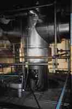
This is a prototype of the four-stage cryogenic liquid turbine installed for National Helium Corp. at its Liberal, Kan., plant in June 1989. It increases helium recovery by 6.25% over use of a conventional JT valve and generates 600 kw/hr directly into the plant's power grid (Fig. 2).
A four-stage cryogenic liquid turbine was ordered by Air Products for National Helium Corp., Liberal, Kan., in June 1989 (Fig. 2).
This single turbine was designed for 410 l./sec. When used in place of the JT valve, it increases the helium recovery from an LNG stream by 6.25%. It also reduces the overall plant energy costs by about 600 kw/hr.
The unit has more than 5 years of continuous operation. De-bugging problems centered on the 700 kw, 3,600-rpm electric motor used as a generator and in obtaining a suitable mechanical seal design and support system.
Both problems were resolved.
The electric motor/generator was replaced with a unit designed as a generator. This design, as developed for MLNG-Dua (2), Bintulu, Malaysia, can take full runaway rpm and is built with two full pivot shoe Kingsbury thrust bearings (one for down thrust and a second for up thrust) as well as Kingsbury six-shoe tilting pad journal bearings.
The generator was tested to 7,500 rpm to simulate runaway speed plus a 15% safety margin.
The double mechanical seals developed by BW/IP Seal Division as a result of 5 years' field experience provide for system-upset conditions to 1,000 psi, although they operate at near 160 psi because of the new self-equalizing buffer fluid (synthetic Aeroshell No. 31) support system. There has never been buffer fluid leakage into the process stream.
First production
Eight 800-kw turbine generators were ordered for MLNG-Dua in July 1992: two turbines each for Trains 4, 5, and 6, plus two warehouse spares. The total design capacity for the three trains is approximately 8.0 million tons/year.
Fig. 3 [114464 bytes] illustrates the six-stage turbine sectional drawing.
Fig. 4 [23011 bytes] shows a typical six-stage turbine performance curve. Note that because of the turbine's adjustable wicket gates, it can be set while in operation for a wide range of performance conditions without significant efficiency changes.
This 800-kw turbine and 6,600 v, 50 cycle induction generator were installed for the MLNG-Dua project, Bintulu (Fig. 5).
Fig. 5 shows an installed turbine and 6,600 v, 50 cycle, 800-kw induction generator at the Bintulu site.
All eight turbines were tested at full flow and pressure head on -160° C. LNG test liquid. The turbines, tested over a range of anticipated field conditions, absorbed the pressure letdown of the product streams, removing 77-85% of the total energy involved.
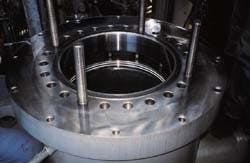
The double-wall barrel allows both suction and discharge piping to be completely installed before the turbine installation (Fig. 7).
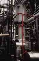
Testing was conducted in July and August 1993 in Costa Mesa, Calif. Fig. 6 [112506 bytes] shows the test piping profile. Fig. 7 looks down into the unique double-wall barrel which allows both suction and discharge piping to be completely installed before the turbine installation.
During actual testing, all piping ran at full -160° C. temperature. The turbines were powered by the world's second largest LNG pump which, in turn, was driven by a 1,500 hp variable-speed electric motor.
Turbine efficiencies were determined by the kilowatts generated vs. inlet and outlet pressure differentials at various measured flows. The test engineer fine-tuned the wicket gates during operation for maximum kilowatts. The more kilowatts he was able to develop for any given set of test conditions, the better the process efficiency became.
Each turbine generator was tested for a simulated runaway. This occurs when the generator has an emergency disconnect from the power grid (vs. a planned shutdown) with full flow and process system pressure still driving the unit.
The turbines reached speeds of 5,000-5,600 rpm, depending on actual test conditions that prevailed. The generators alone, while under test at their manufacturing plant, were further over-speeded to about 6,800 rpm.
An important facet of this runaway testing was to measure the product flow through the turbine to determine the runaway throttling characteristic (often called the "choke-flow").
Conventional Francis-type turbines as well as 1,500-2,500 specific-speed pumps (running in reverse as turbines) will instantly (5-10 cycles of a 50-cycle sec) throttle the process flow by 35-50%. This "choke-flow" would create significant concerns for plant process engineers and operators.
The actual testing of the LNG turbines exhibited no more than 10-15% throttling choke-flow with full pressure differential at runaway speeds.
At MLNG-Dua
All eight units for MLNG-Dua in Bintulu shipped per schedule between September and December 1993.
The first two turbines, for use in Train Four, were installed at Bintulu in December 1994. They were started up successfully in early spring 1995.
All three MLNG-2 Bintulu trains are now operating successfully. Six hydraulic turbines, two per train, are in full operation around the clock.
Based on the successful operation of MLNG-Dua, plans currently under development for the third phase of the Bintulu operation, called MLNG-TIGA (3), also include hydraulic turbines to be used as liquid expanders.
Based on the success of the installations in Kansas and Bintulu, four cryogenic hydraulic turbine expanders have been ordered for installation in a new LNG liquefaction plant in Nigeria.
These turbine expanders are scheduled for testing in the first quarter of 1997.
What's been learned
The use of hydraulic turbines to bypass the JT valves can provide an increase in product revenue of 3-6%, depending on the number of turbines applied per train.
The technology has proven to be fully safe and reliable. With near neutral flow at runaway speeds, operation at runaway speeds is safe and continues to maintain pressure breakdown.
The use of hydraulic turbines provides significant flexibility to changes in production rates and/or available letdown pressures as a result of the variable wicket-gate settings during operation.
Advantages in the design provide for elimination of seal-oil contamination; and no cooling water is used on the turbines, mechanical seals, or generator.
Other advantages include the reduction of LNG flaring to improve environmental concerns and the elimination of JT cavitation noise while the turbines operate at 85 db or less.
Considerable generation of electrical power into the plant grid system and an investment payback within 6-12 months of operation are also attractive benefits of this technology.
These many potential benefits of using hydraulic turbines in LNG liquefaction are applicable to new LNG projects as well as to existing plants where debottlenecking and efficiency gains are important goals.
The Authors
L.L. "Johnny" Johnson has been with the pump division of BW/IP International Inc. for 45 years. In the past 10 years, he has concentrated on the development of hydraulic turbines, particularly for cryogenic applications. Before retiring in 1995, his most recent position with BW/IP was manager, cryogenic products. He held previous positions in sales and product management.
Johnson has made frequent technical presentations worldwide at pump and turbine symposia. He has attended the University of California at Los Angeles and taken many technical short courses.
Gerard Renaudin is chief engineer in the process and technology division of Technip (France) where he has worked since 1969. He currently leads Technip's LNG group. Renaudin graduated as an engineer from the Ecole Nationale Suprieure Electrochimie, Electromtallurgie, Gnie Chimique, and from E.N.S. du Ptrole et des Moteurs. He is involved in the Association Francaise des Techniciens du Ptrole (AFTP), Association Technique de L'industrie du Gaz en France (ATG), the European Chapter of Gas Processor Association, and Commission A3 of the International Institute of Refrigeration.
Copyright 1996 Oil & Gas Journal. All Rights Reserved.
