TECHNOLOGY Compression decks extend production platform life
Ian Mackenzie Peter
Brotherhood Ltd.
Peterborough, U.K.
Installation of cantilevered compression decks on two North Sea platforms has extended their productive lives.
The decks afforded space for gas treatment and compression of process gas to fuel turbine generators in processes that inject water to maintain producing-formation pressures.
The two projects, for Shell U.K. Exploration & Production (Shell Expro), represent efforts by platform operators in the North Sea and elsewhere to maximize returns by concentrating activities onto fewer platforms and extending the life of existing fields with introduction of new equipment.
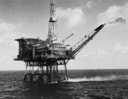
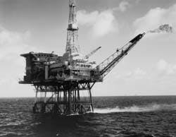
Shell Expro's Auk Alpha platform in the U.K. North Sea has been producing oil since 1975 (Fig. 1).
Auk field
The North Sea's Auk oil field lies 250 km east southeast of Aberdeen (Fig. 1). Oil companies Shell Expro and Esso Exploration & Production U.K. have been extracting oil since 1975 and, since 1986, exporting it by pipeline to the nearby Fulmar field for collection by tanker. Previously, tankers had taken oil directly from Auk.
Peak production from the Auk field was in 1977 when it delivered 17.5 million bbl (2.3 million metric tons) of oil. By 1990, annual production had fallen to 3 million bbl (411,000 metric tons).
As reserves were depleted, it began to look as though Auk field operator Shell would have to withdraw. Falling field gas pressures meant that recovery of oil was becoming increasingly difficult, as the natural flow of oil is in proportion to the well pressure.
Geologists estimated, however, that the total recoverable reserves were probably still on the order of 88 million bbl (12 million metric tons) of oil.
Rather than cap the wells and close Auk production facilities, Shell invested in water-injection equipment to boost the natural pressure in the wells and hence increase the flow of oil. Shell estimated that this strategy should give the platform a further 10 years of productive life.
Although the water-injection equipment adds considerably to the electricity demands on Shell's Auk Alpha platform, all the power is provided by the platform's three original 1.2-mw Ruston gas turbines.
These are fueled by process gas provided by the production separators, as they have since the platform began operations.
The gas supply pressure, however, was falling below the minimum required for the turbines, creating an urgent need to compress the gas to return supply pressure above this minimum. Furthermore, the gas now also needed treating to meet the temperature and heating-value requirements of the turbines.
But there was simply no room on the platform for the size of gas compression and conditioning package required.
The solution was to mount the compressor and the gas conditioning plant on a new deck section cantilevered off the existing platform structure. To accommodate this new extension of the platform, the existing flare boom had to be relocated to hang on the end of the cantilever section.
The requirements
Shell set out detailed specifications for the compressor and gas-treatment package. The company then sought proposals from equipment suppliers, asking not only for prices but for details of how suppliers could meet all the specifications while minimizing the package size, power, and utility requirements. Major emphasis was placed on equipment size.
The compressor itself had to be capable of maintaining output over a wide range of fuel-gas input conditions. For example, flow rates were expected to vary between 25.6 and 31.6 normal cu m/min; inlet pressures could vary between 1.28 and 1.98 bara and inlet temperatures could vary from less than 65 C. to more than 74 C.
The composition of the gas was a mixture of water vapor, nitrogen, carbon dioxide, and at least 18 different hydrocarbons. This composition could vary from, for example, 11.2% water to 19.8% water by mass.
The compressor package had to deliver a minimum of 10 bara output to prevent the system being tripped and a maximum of 14.5 bara, with a design pressure outlet for maximum turbine efficiency of 13 bara.
Gas temperatures at the turbine inlet could vary between 30 C. and 70 C., but the key requirement was to ensure 25 C. of superheat. If superheating fell to less than 20 C., the system would again be tripped.
Shell selected U.K. engineering company Peter Brotherhood Ltd. as the supplier for the complete gas compression and treatment package.
Initially, Shell awarded Peter Brotherhood a contract simply to supply the compressor and some associated equipment. As the project progressed, Shell awarded Peter Brotherhood total project responsibility, including all the process and structural design work.
Peter Brotherhood developed a new process simulation package in order to facilitate the process calculations. With so many possible variables in gas composition and state and so many possible variations on gas demand, computer analysis was essential to demonstrate that the package would meet the design requirements in all possible scenarios.
It took 2 months simply to establish the design criteria for all the possibilities.
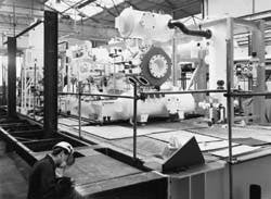
Work on the compressor package for Shell Auk is under way in Peter Brotherhood's works, Peterborough, U.K. (Fig. 3).
The equipment
The complete package of compressor, gas-conditioning equipment, and cantilever deck unit was valued at 1.2 million.
Shell retained consulting engineers Brown & Root Vickers to assess the design and the supporting calculations. All Peter Brotherhood's working drawings and process calculations had to be submitted to BRV for verification before work could begin on building the equipment.
The Peter Brotherhood compressor, a two-cylinder, horizontally opposed reciprocating machine, is driven by a 205-kw electric motor. It is fitted with pulsation dampers, its own sea water-cooled lubrication system, and a water jacket (which also uses sea water) for cooling the compressor itself (Fig. 2 [141366 bytes]).
Although there is no purge system fitted on the machine at present, the compressor has been designed to accommodate a nitrogen purge system if Shell should decide to fit one later in response to changing gas conditions or safety assessments.
After leaving the compressor, the fuel gas is piped to the hot side of the fuel-gas superheater, a gas/gas heat exchanger where it surrenders heat to cold gas leaving the surge drum. It then passes to the after-cooler where it is further cooled and partially condensed to 23 C. at 13 bara using sea water.
The gas and condensate mixture then flows to the surge drum where the gas and liquid phases are separated. The gas phase leaving the surge drum is superheated to 25 C. above its dew point in the fuel gas superheater, drawing heat from the hot gas leaving the compressor, as noted.
It is then filtered to remove any solid particles or remaining liquid droplets before being piped to the flare pilots and the gas turbines.
Depending on the gas composition and the operating conditions, the condensate leaving the surge drum flows either to the condensate header tank or the second-stage scrubber. This is an inter-cooler and separator between the first and second stages of the compressor.
From there, it can be recycled back into the fuel stream. As much as 75% of the mass flow can be removed as condensate under typical flow conditions.
The discharge pressure of the compressor package is controlled by recycling gas from downstream of the filters, through a pressure control valve, back to the first stage of the compressor. To allow for any sudden increases in pressure (such as might be caused by failure of one of the gas turbines), a pressure dump valve permits the gas flow to be vented to the gas flare where it can be burned.
Depressurization valves are provided which depressure the entire gas compression and treatment package automatically when signaled by the platform's central control system. The valves are also designed to ensure that all parts of the system are automatically reduced to 50% of design pressure (or 8 bara if this is lower) within 15 min of exposure to fire.
Peter Brotherhood designed, fitted, and tested fire and gas detection equipment and a complete deluge fire-fighting system as part of the package, which is fitted with its own control and instrumentation systems linked to the central control room on the platform.
All the equipment has been designed, tested, and certified according to many standards specified by Shell, including those issued by the U.K. Department of Energy, ISO, BSI, ANSI, API, ASTM, and Shell itself.
Although the compressor is actually operated in a Zone 2 hazardous area, all the electrical equipment on the package has been designed to meet the more demanding "Zone 1" requirements for areas in which explosive gas-air mixtures are likely to occur in normal operation. (Zone 2 areas are those in which such conditions are possible but unlikely during normal operation.)
Higher standards of electrical insulation, among other construction elements, are required in Zone 1 areas to reduce risks of sparks or other sources of ignition.
Moreover, because of the exposed conditions with the package situated on a cantilever beyond the edge of the actual platform deck, equipment, piping, wiring, and instrumentation have all been designed and built to withstand the worst North Sea weather over the equipment lifetime.
All the structural steel on the package, for example, is of a grade which gives the design level of impact resistance down to temperatures of -40 C.
Installing the deck
The cantilever deck unit itself has been designed to meet stringent structural safety requirements. It is also capable of being attached to the side of Shell's Auk platform using a floating crane (the MSV Stadive) with a maximum 80-metric ton lift. Even in calm summer weather, attaching the cantilever was difficult.
The approach adopted was to provide the cantilever platform with two "rakers" which ended in massive pins.
A raker is an inclined structural member, fixed to the cantilever deck unit at one end and carrying a pin-like attachment at the other. These pins locate into hooks attached to the platform structure in order to secure the cantilever deck in place.
When the cantilever was hoisted into place, these were located in two hooks attached to the existing platform superstructure.
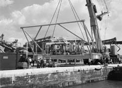
Because the package was already as wide as could be moved legally on U.K. roads, fitting the rakers had to be undertaken at the dockside at Boston, Lincolnshire, from where the package was shipped (Fig. 4). Although performed in the open, welding had to be of the highest quality and thoroughly tested.
To preclude last-minute problems, Peter Brotherhood undertook a trial fit of each of the pin and hook joints before shipping the unit. In fact, the company constructed a replica of part of the Shell Auk Alpha platform on the dockside at Boston to ensure that the cantilever would fit perfectly into the mountings designed to secure it.
The overall dimensions of the cantilever section were strictly controlled.
To ensure that the distance between the pins on the ends of the rakers matched the location of the hooks on the platform to within the specified 1 mm over the 12 m between them, the deck unit was built in two halves, and a carefully machined distance piece was then inserted between the sections to give the precise completed dimension.
Once installed on the platform, the cantilever was accessible by the crane already installed on the deck above, necessary to provide for future removal of any piece of equipment for major overhaul or replacement.
This meant that the cantilever deck section had to be provided with a roof to protect against accidental damage from falling objects.
Walkways, railings, and the roof had to be designed, manufactured, and shipped with the cantilever platform itself. They were then erected and installed once the cantilever platform was in place.
Shipping the unit with these components in place would have made it too large for road transport and too heavy to be lifted by the floating crane: overall the cantilever deck section fully assembled measures around 14 m long, 7 m wide, and 5 m high and weighs around 120 metric tons.
Once the cantilever deck was ready for shipping, it was lifted aboard the supply vessel MV Stirling Osprey and taken out to sea for shipment to the MSV Stadive.
Peter Brotherhood was responsible for providing secure lifting points on the cantilever deck: one of the design team's worst nightmares was that the package would fall from the crane into the sea alongside the platform during installation.
The company was also responsible for providing detailed calculations of masses and centers of gravity to allow the design and construction of suitable lifting equipment.
It was essential that the cantilever deck be correctly positioned in relation to the platform when it was lifted by the floating crane. Otherwise it would be impossible to locate the pins on the rakers into the hooks on the platform.
The structural design of the cantilever deck section had to take into account not only the forces that it would be exposed to in situ but also those experienced during the installation. Complex finite element analyses were carried out to check the structural integrity of the unit under all possible circumstances during installation.
All the calculations proved to be accurate. The package was successfully positioned on Auk Alpha during the brief "weather window" in the summer of 1992 and is now operating fully.
Lifting on the docks in Boston, U.K., begins on the compressor package for the cantilever platform (Fig. 4).
Shell Cormorant
Following successful completion of the Shell Auk project, a further reciprocating compressor package was commissioned in 1994 for installation elsewhere in the North Sea. The new package drew heavily on the experience gained in the earlier project.
Shell's Cormorant Alpha platform was installed in 1978 to collect oil and gas from the Cormorant and other fields and to maintain formation pressure by water injection.
During 1995, Shell Expro, operator in the U.K. sector of the North Sea for Shell and Esso, modified and replaced existing facilities on the Cormorant Alpha platform to take oil and gas from the nearby Pelican field.
Pelican oil is now separated from the gas and exported by the Brent system pipeline to the Sullom Voe terminal on the Shetland Islands. The gas, after processing on the platform, is piped via the Far North Liquids and Gas System (Flags) pipeline to the St. Fergus (Scotland) gas terminal.
Falling natural-gas pressures meant that gas coming from the second stage oil/gas separators was no longer at a pressure high enough to be accepted by the inlet of the centrifugal compressor used for gas export from the platform.
Without compression, the excess gas would have to be flared. This would be both environmentally and commercially undesirable.
A booster compressor was therefore required, and Shell again turned to Peter Brotherhood to provide the equipment.
With the new compressor package in place, gas from the separator now flows to a suction cooler where it is cooled and partially condensed to 30 C. The resultant two-phase stream flows to the suction of the booster compressor, a two stage, two-crank reciprocating machine powered by a 260-kw electric motor.
The first stage lifts the pressure from 1.5 bara to 3.3 bara at a temperature of 57 C. The second stage produces the delivery pressure of 7.0 bara at 88 C. The gas then mixes with the suction stream of the centrifugal gas lift/export compressor.
The gas mixture being handled by the compressor can vary widely. At maximum mass flow conditions, at which the compressor has a rated capacity of 6,776 kg/hr, the gas comprises around 27% propane and 17% each of methane and butane with a mixture of other hydrocarbon gases.
This is just one of many possible conditions, however, in which the gas may be delivered to the compressor, all of which had to be considered in the design calculations.
The mixture can also contain around 200 ppm of hydrogen sulfide; all compressor components that come into contact with the working fluid therefore have to be made of materials which resist corrosion.
Simulations
Rating and sizing calculations were undertaken by computer to ensure the most economic sizing of the compressor in terms of power and performance under all running conditions.
Finite element analysis, piping stress analysis, acoustic modeling, full 3D computer-based color modeling, and other computer-aided design tools were used by Peter Brotherhood to optimize design of the complete gas compression and treatment package.
Sophisticated process simulation programs, developed as part of the Shell Auk contract, were used to perform complete heat and mass-balance calculations and permit precise modeling of the state of the gas at all stages of treatment and compression.
Computers were also used to model the vibration behavior of the compressor. Along with tight dimensional constraints and the need to meet various international, national, and industrial standards, Shell imposed tight limits on acceptable levels of vibration.
The compressor pistons were carefully balanced to eliminate out-of-balance forces, and a special crankshaft with additional balance weights was used to reduce out-of-balance couples. The compressor was then mounted on three resilient mountings to reduce the transference of any remaining vibration to the superstructure of the rig.
The 600,000 Peter Brotherhood gas compression and treatment package forms part of a replacement process module which also contains the oil/gas separators and centrifugal gas lift/export compressor and associated equipment.
The module was built by AMEC Process & Energy Ltd. in its yard at Wallsend on Tyneside where the Peter Brotherhood compressor was delivered early in 1995. It was successfully installed on the Cormorant Alpha platform in the U.K. North Sea in the summer of 1995 and is now operational.
The Author
Mackenzie
Ian Mackenzie is a product manager and chief design engineer of the compressor division of Peter Brotherhood Ltd., Peterborough, U.K. He joined the company as an apprentice in 1967 and, upon completion of his apprenticeship in 1973, joined the compressor division as a design engineer. He became senior design engineer in 1977 and was appointed chief design engineer in 1982. He was subsequently promoted to manager of the division in 1987.
Copyright 1996 Oil & Gas Journal. All Rights Reserved.
