TECHNOLOGY Thermoplastic film prevents proppant flowback
Philip D. Nguyen, Jimmie D. Weaver, Mark A. Parker, Dwain G. King
Halliburton Energy Services
Duncan, Okla.
Temperature Influences Thermoplastic Film
Thermoplastic film added to proppants is effective and economical for preventing proppant flowback after an hydraulic fracturing treatment.
Most other methods, such as resin-coated proppant and fiber, for controlling proppant flowback have drawbacks that add to treatment costs by requiring long downtime, costly additives, or frequent equipment replacement.
Thermoplastic film does not react chemically with fracturing fluids. After the proppant is placed in the fracture, the film strips intertwine with the proppant grains or at higher temperatures, the strips become adhesive and shrink forming consolidated clusters that hold open the newly created fractures and prevent proppant from flowing back.
The low cost of the film means that the strips can be used throughout the fracturing job or in selected stages. The strips are compatible with fracturing fluid chemistry, including breakers and crosslinkers, and can be used in wells with a wide range of bottom hole temperatures. The end result is a well that can be brought back on-line in a short time with little proppant flowback.
Thermoplastic film processed for a fracturing application costs about 50-70% of the material used in resin-coated proppant treatments.
Flowback control
During hydraulic fracturing treatments, proppant grains suspended in a viscosified fluid are pumped into created fractures.
When the pumping pressure is released, the proppant remains in the fractures, holding the fracture open and forming a conduit for fluid flow into the well bore. If the proppant flows back into the well bore, the fracture channel width will decrease. Less proppant in the fracture limits the flow channel conductivity, reducing the effectiveness of the fracture treatment.
Also, produced proppant can erode production equipment, requiring costly repairs and frequent downtime.
Variations in formation in situ stress and mechanical properties can lead to nonuniform fracture closure and open channels above the proppant pack.1 Fluid tends to flow preferentially along such channels, and the high velocities may increase the tendency of proppant detachment and flowback in this region.
Screens or slotted liners in the well bore can stop proppant or formation materials flowback; however, this equipment limits the production rate particularly when the screens become plugged with scale, formation debris, proppant, and corrosion products. This method can be expensive if the screens require replacement.
In the forced closure technique, the treating pressure is released as soon as the pumping of displacement fluid is complete. Ideally, the fracture closes while most of the proppant is still suspended across the pay zone, preventing the proppant from settling at the bottom of the fracture. A disadvantage of this technique is the possibility of back production of proppant into the well bore.
Resin-coated proppants
Curable resin-coated proppants help control proppant flowback by forming a consolidated sand pack in the formation. The resin contained on the proppant cures at formation temperatures and pressures, forming bonds between individual proppant grains.
The high cost of resin-coated proppant limits its use to the tail-in stage on the last 5 to 25% of the proppant placed. However, resin-coated proppant is not always effective at curtailing proppant flowback.
In the past, operators believed resin-coated proppant systems with high bonding strength between the grains would keep the proppant in the fracture. However, research2 shows that the benefits of resin material are not long-lasting under reservoir conditions.
The resin coating has a tendency to affect fracture conductivity, and the resin coating can chemically interact with common fracturing fluid systems, such as guar or hydroxypro pylguar with organometallics or borate crosslinkers. This interaction results in altered crosslinking and break times for the fluids, which affects proppant placement.1-3 Resin also requires a downtime of 12-48 hr to cure, further adding to operating costs.
The insufficient strength of the resin-coated proppant allows proppant flowback during the cleanup phase before production resumes. Proppant flowback that occurs after a long period of proppant-free production is mainly caused by stress cycling on the proppant pack as the well is shut in and put back on production.
Curable resin coatings affect break times by releasing chemicals that affect the proppant pack characteristics and fracturing fluid behavior.3 Curable resin-coated proppant also is incompatible with oxidizing breakers. The resins release phenols and creosols that react with the breakers.4 Adding more breaker to the fracturing fluid helps minimize the problem but also adds to the overall treatment cost.
Fiber additives
Soil conservation agencies use synthetic fiber-mesh mats to keep soil in place and avoid natural disasters caused by flooding, landslides, and soil erosion.5 6 Fluids move freely through the fiber mesh without disturbing the soil particulates. Blending of fiber material with cement provides additional strength and resiliency in roads, bridges, highways, and residential driveways.6
The oil industry has used synthetic fibers in isolating zones, reducing cement sheath shattering from perforating, improving bonding, and controlling fluid loss during cementing.7 8
Fiber also has been used to try to overcome proppant flowback by incorporating the fibrous material into the proppant fracturing fluid.9 The fibers bridge across the proppant pack and form a framework that holds the particulates in place and limits proppant production. One disadvantage of this method is that the fibers break because of their small diameter.
Glass fiber tends to break into small fragments when sheared by the pumping equipment. The broken fiber fragments produce a weakened framework in the fracture. The fragments and fibers produced out with the fracturing fluid can cause plugging problems.
Thermoplastics
Strips of thermoplastic film or polyolefin material offer an economical method of inhibiting proppant flowback after fracturing. When the material has been pumped downhole and is in the fracture with the proppant, the film strips intertwine with the proppant grains and form consolidated clusters that hold open the newly created fractures and prevent the proppant from flowing back.
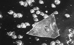
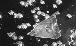
The film strips or flakes can be used throughout the fracturing job or in selected stages, and the material is compatible with all breakers. The material also helps to absorb the shock of the stress cycle when the well is put in production and shut down. At low temperatures, the material provides a high-friction surface that minimizes the rolling tendency of the proppant in the producing stream (Fig. 1).
Thermoplastic film strips at ambient temperature provide a high-friction surface that minimizes the rolling tendency of the 20/40 mesh proppant (Fig. 1).
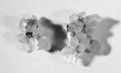
At high temperatures, film adhesion and shrinkage hold the proppant in place. The proppant adheres to the surface, forming small clusters of sand grains (Fig. 2). These sand clusters are located randomly through the segment of fracture that is near the well bore or throughout the fracture length, depending on treatment design.
Between 0.25 and 1% of the proppant weight of the thermoplastic material can be blended with the proppant slurry "on-the-fly" during the entire fracturing treatment or during the tail-in stage. The film strips can be added to the fracturing fluid with either a dry additive feeder or a sand screw.
At high temperatures (275 F.), thermoplastic film strips adhere to the surface of the 20/40 mesh proppant, forming small clusters of sand grains (Fig. 2).
Small quantities of film strips can be added to the sand screw manually. The strips then are carried into the system with the sand.
Setting the load factor on one of the screws allows the screw to meter the material automatically into the tub at the correct material-to-proppant ratio. If the proppant concentration changes during the thermoplastic stage, such as during a ramp, the sand screw will maintain the correct ratio based on the load factor.
With the dry additive feeder, the set points change as the proppant concentration changes to maintain the required ratio.
Strip size determines the effectiveness of the proppant flowback control and the conductivity of the proppant bed in the fracture. The film strips must be long enough to allow several sand grains to adhere to the same surface, adding more resistance and creating long clusters of sand.
There are advantages of using thermoplastic film strips over traditional methods:
- The film does not react with other additives and does not affect the chemistry of the fracturing gel.
- The strips remain stable in water, oil, and acid.
- Thermoplastic material is economical, meaning that the system can be used throughout the fracturing treatment.
Laboratory testing
Flow tests conducted in an unconfined, sand-packed flow cell and in an API linear flow cell determined the effectiveness of thermoplastic film strips in controlling proppant flowback. The tests showed that the thermoplastic film strips increased the critical flow velocity for proppant flowback in both test cells.
A mixture of 20/40-mesh Ottawa proppant and thermoplastic film strips (1% by weight of proppant) was packed in the unconfined flow cell. The flow test was performed at 75 F. without closure stress applied (Table 1 [16852 bytes]).
In the API linear flow cell, a similar proppant and thermoplastic film strip mixture was placed in the cell at a concentration of 2 lb/sq ft. The flow test was performed at 75 F. with a closure stress of 2,000 psi (Table 1 [16852 bytes]).
The conductivity tests with 20/40-mesh Ottawa sand at 75 F. and at a loading concentration of 2 lb/cu ft showed that the thermoplastic strips did not affect the proppant bed conductivity.3 At 275 F., the thermoplastic material started to reduce the proppant bed conductivity as the concentration exceeded 0.5% by weight. The tests determined that thermoplastic strip concentration should not exceed 1% by weight of proppant. At temperatures above 350 F., the film melted.
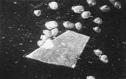
The thermoplastic film was pumped and circulated through a lab-scale centrifugal pump to examine the stability. The strips remained intact after pumping and circulating, and there was no sign of wear on the original structure (Fig. 4).
Lab tests showed that the thermoplastic film remained intact after pumping and circulating through a centrifugal pump (Fig. 4).
Field examples
One operator stimulated 29 gas storage wells in 1994. The bottom hole temperature was 120 F. at about 6,000 ft. The fracturing treatments increased average production by 3.5-fold, but more than half the wells experienced erosive failure of the flowback manifolding caused by proppant production.
In 1995, eight of the wells were restimulated with the thermoplastic film system. All other treatment factors were the same as in the 1994 stimulation program. None of the eight wells experienced erosive failure, and the wells averaged a production increase of 4.5 fold.
In another case, a South Texas operator treated two of seven wells with thermoplastic film strips in the final proppant stage. The two wells treated with thermoplastic film flowed an average 2.28 MMcfd after cleanup, while the other five wells averaged 2.32 MMcfd. But the wells treated with thermoplastic film produced proppant-free after an average of 30 hr, while the wells without thermoplastic material averaged 141 hr before producing proppant-free.
The flowback rates during cleanup on the wells without thermoplastic material were 35% lower than the wells treated with the thermoplastic strips. The untreated wells produced 25 times as much proppant as the wells treated with the thermoplastic strips.
Bottom hole temperatures ranged from 220 to 260 F. at 7,000-10,000 ft. Closure stresses ranged from 5,000 to 8,000 psi.
References
1. Milton-Tayler, D., Stephenson, C., and Asgian, M.I., "Factor Affecting the Stability of Proppant in Propped Fractures, Results of a Laboratory Study," Paper No. SPE 24821, SPE Technical Conference and Exhibition, Washington, D.C., Oct. 4-7, 1992.
2. Vreeburg, R.J., Roodhart, L.P., Davies, D.R., and Penny, G.S., "Proppant Back Production During Hydraulic Fracturing, A New Mechanism for Resin-Coated Proppants," JPT, October 1994, pp. 884-89.
3. Norman, L.R., Terracina, J.M., McCabe, M.A., and Nguyen, P.D., "Application of Curable Resin-Coated Proppants," SPE Production Engineering, November 1992, pp. 343-49.
4. Terracina, J.M., and Parker, M.A., "Resin-Coated Proppants," Stimulation Technology Review, No. l, 1994, pp. 81-87.
5. Godehn, D.J., "Nylon Matting, A Textile Structure Used for Soil Conservation and Civil Engineering Applications," Polymer Engineering and Science, No. 17, 1977, pp. 317-19.
6. McGuffy, V.C., "Filter Fabrics for Highway Constructions," Highway Focus, No. 10, 1978, pp. 1-21.
7. Smith, D.K., and Carter, L.G., Well Cementing, U.S. Patent No. 3,363,689, 1968.
8. "Tuf Cement Composition," Halliburton Service Cementing Technical Data, C-1207.
9. Howard, P.R., King, M.T., Morris, M., Feraud, J.P., Slusher, G., and Lipari, S.A., "Fiber/Proppant Mixtures Control Proppant Flowback in South Texas," Paper No. SPE 30495, SPE Technical Conference and Exhibition, Dallas, Oct. 22-25, 1995.
The Authors
Philip D. Nguyen is a senior engineer II in the stimulation engineering and applications group at Halliburton's technology center in Duncan, Okla. Since joining Halliburton, he has worked in various areas of sand control, conformance, completion, and stimulation research. He has been involved in new product development and application.Nguyen holds a PhD in chemical engineering from the University of Oklahoma.
Jim Weaver is a principal scientist III in the stimulation chemicals department of Halliburton's technology center in Duncan, Okla. His principal area of expertise is in polymer science, especially as applied to clay treatment, fluid rheology modification, EOR, and plastics.
Weaver holds a BS in chemistry from Southwestern Oklahoma State University, and a PhD degree in organic chemistry from Oklahoma State University.
Mark Parker is a senior technologist III in the stimulation engineering and applications group of Halliburton's technology center in Duncan, Okla. In his 16 years with Halliburton, Parker has specialized in stimulation; his current area of interest is fracture conductivity measurement. He holds a BS in geology from the University of Wisconsin and is a member of SPE and AAPG.
Dwain G. King is a technology consultant in stimulation technology with Halliburton Energy Services in Duncan, Okla. King has more than 23 years of experience in stimulation, cementing, and downhole tools in the Gulf Coast, North and East Texas, and in the Rocky Mountain area. He holds a BS in industrial engineering from Texas A&M University.
Copyright 1996 Oil & Gas Journal. All Rights Reserved.
