Double mixed refrigerant LNG process provides viable alternative for tropical conditions
Based on a presentation to 82nd Annual GPA Convention, Dallas, Mar. 11-13, 2002.
A comparison of LNG processes for tropical conditions showed that Shell double mixed refrigerant (DMR) process is a competitive alternative for the propane mixed refrigerant (C3MR) process. For both processes, an end-flash system provides many advantages.
Production capacity is 10-15% higher for the same gas turbine compressor drivers (two General Electric Frame 7s) and helper motor sizes. Corresponding specific costs are 6-8% lower. For single-train developments, these differences can translate into $150 million additional net present value (NPV) over the project's lifetime.
The DMR process was first selected for the arctic conditions of the Sakhalin LNG project. In this article, we assess the process for tropical conditions, typical for many LNG projects. We compared the two processes in terms of LNG and LPG production rates, specific refrigeration power, and specific costs.
Background
Operators in the competitive LNG market continuously strive to lower specific costs. They must select the best liquefaction process since the liquefaction section accounts for about half the capital costs of an LNG plant.
The propane precooled, mixed refrigerant (C3MR) process is the workhorse of the LNG industry. Some recent projects, however, have used other processes. For example, the Atlantic LNG project used Phillips Petroleum's optimized cascade process and the Sakhalin LNG project used the DMR process.1 2
As a follow up to a process comparison for the arctic conditions of Sakhalin, we decided to compare the C3MR and DMR processes at tropical conditions, which are typical for many LNG projects.
We performed the study within the framework for a Shell-advised LNG plant; the operator was considering an expansion of one or more LNG trains. The results and conclusions, however, are generally applicable.
Six options were evaluated, ranging in LNG production capacity from 3.4 to 4.3 million tonnes/year (tpy):
- Base cases-C3MR basic and DMR basic. These are the simplest options, with a focus on minimizing equipment and capital expenditure. Features are simple fractionation, no reinjection from the fractionation unit, no end-flash, and minimal power requirements.
- End-flash cases-C3MR end flash and DMR end flash. Adding an end flash to the base cases can raise LNG and LPG production rates. One must balance the value of additional production against additional capital costs and electrical power requirements for the end-flash compressor.
- Extended end-flash cases-C3MR extended and DMR extended. The end-flash system is larger to produce fuel gas beyond the needs of the new process trains. Surplus fuel gas is exported to existing LNG trains, which do not have end-flash systems. Fuel gas production in the latter trains decreases accordingly. The extended end flash enhances the new trains' capacity and also helps debottleneck existing trains.
We compared the different options in terms of:
•LNG and LPG production capacities.
•Power requirements and specific power.
•Capital and specific costs.
•Preliminary economic screening-NPVs.
Methodology
For consistency, we assumed similar gas pretreating for all options consisting of an amine absorption process for acid-gas removal, a conventional three-bed dehydration unit, and a mercury guard bed.
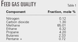
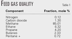
Air cooling is used. The average ambient air temperature is 28.5° C. We chose approach temperatures to optimize available plot space. Table 1 shows an average feed gas quality.
Two General Electric Frame 7 gas turbines with starter-helper-generator motors were the drivers for the precooling and mixed-refrigerant (MR) liquefaction circuits.
The LPG fractionation units produce export-grade propane, butane, and condensate. The process did not need additional refrigerant-grade ethane and propane production.
Normalized capital-cost estimates and NPVs refer to a single-train expansion. For the different options, we prepared full-cost estimates based on detailed equipment information and considered the impact of process choice on utilities and refrigerant storage requirements.
An important aspect of this particular case study was to stay within the boundaries of proven technologies, but to incorporate appropriate technological enhancements to ensure the new design's economy and competitiveness.
The C3MR options resembled a process lineup of recent air-cooled designs such as MLNG Tiga.3 The DMR options essentially used the same process lineup developed for the arctic conditions of Sakhalin LNG.
The design premises limit LNG production to 3.4-4.5 million tpy. Increased helper motor power, alternative gas turbines, or electric motor drives can increase the capacity to 4.5-5.5 million tpy.4
C3MR process
The C3MR process consists of two refrigeration cycles: a propane-refrigeration cycle to cool from ambient conditions to 235° C., and MR cycle to liquefy the natural gas stream and subcool it to 2160° C.
With an end-flash system, the degree of subcooling is reduced to 2150° C. With extended end flash, subcooling is reduced to 2145° C.
The propane cycle has four pressure levels for precooling the natural gas and MR streams. The MR stream is separated into a light stream and a heavy liquid stream after it is cooled to the low-pressure propane temperature level.
The heavy MR stream is subcooled in the warm and middle bundles of the main cryogenic heat exchanger (MCHE). The stream is then let down in pressure in a liquid expander and routed to the MCHE's shell side.
The light MR stream is liquefied and subcooled in the MCHE's warm, middle, and cold bundles. The stream is then let down in pressure and routed to the MCHE's shell side.
NGLs are separated from relatively rich gas in the scrub column. Low-pressure propane and the warm MCHE bundle provide overhead cooling. NGLs are then routed to the fractionation unit.
In the base case, the C2- cut is used as high-pressure fuel gas. In the extended end-flash cases, it combines with the main natural gas stream.
Propane, butane, and condensate from the fractionation unit proceed to the storage and loading area for export. A liquid expander reduces the pressure of subcooled natural gas from the MCHE. The natural gas stream is flashed to atmospheric pressure in the extended end-flash cases. The process recovers cold from the generated vapor and compresses the gas to high-pressure fuel level.
Shell DMR process
The main difference between the Shell DMR and the C3MR process is the precooling mixed-refrigerant (PMR) cycle. In the DMR process, the precool refrigerant is a mixture of ethane, propane, and small amounts of methane and butane.
Spool-wound heat exchangers replace most of the kettles in the C3 cycle. The scrub column overhead requires no additional MR cooling since the PMR cycle can reach a precool temperature of 240° C., which leads to a simpler lineup.
The DMR process has less equipment than the C3MR process. The process has more flexibility, which allows a wide range of operating conditions.
Process comparison
Table 2 shows production capacities, relative capital costs, relative specific costs, and specific powers for the various cases.
Production capacities
The C3MR base case has an LNG production capacity of 3.4 million tpy, based on 340 stream days, and an LPG capacity of 0.3 million tpy for an LNG plus LPG production capacity of 3.7 million tpy.
The DMR base case has an LNG capacity of 4.0 million tpy, an LPG capacity of 0.3 million tpy, and an LNG plus LPG capacity of 4.3 million tpy, 15% more capacity than the C3MR process.
Production is higher because the precool cycle has the flexibility to allow full exploitation of all gas turbine and helper motor power (80 Mw). Compression power is limited in the propane cooling cycle due to compressor head and suction flow limitations. The DMR process, therefore, has 11% more exploitable power than the C3MR process.
The base DMR process has 4% better specific power than the basic C3MR process. For the extended end-flash cases, the DMR production benefit falls to 10% because the difference in DMR and C3MR specific powers is significantly lower.
Capital costs, NPV
The base DMR capital cost estimate is 5% higher than the base C3MR option (Table 2). DMR with end flash is also 5% more expensive than the C3MR end-flash case.
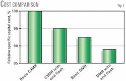
Specific costs of the base DMR option, however, are 8% better than C3MR due to the production increase. DMR with end flash has a 6% lower specific cost than the C3MR case.
Fig. 1 shows relative specific cost for the four options.
The simplified NPV calculations show similar conclusions-the base DMR process has a 61% higher NPV than the C3MR option. The DMR with end flash has a 35% higher NPV than the C3MR end-flash case and 88% higher than the base C3MR option.
For a single-train expansion, the DMR with end flash has an additional NPV of some $150 million over the project's life vs. the C3MR with end flash.
Benefits of end flash
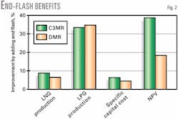
Fig. 2 shows the improvements of adding an end flash to either basic option.
Production increases significantly for both processes. LNG capacity increases 12% and LPG capacity increases 34% for the C3MR process. For the DMR process, these improvements are 6% and 35%, respectively. The large LPG increase results from the C3+ specification of the LNG product.
Although the absolute capital costs increase 3-4%, specific costs improve 6% for C3MR and 4% for the DMR process. NPV over the 20-year project lifetime increases 39% for the C3MR and 17% for the DMR process. This corresponds to about $100 million of additional NPV for a single train (Fig. 2).
Alternative technology
We compared the six cases to an alternative technology, the Phillips optimized cascade process, as applied to the Atlantic LNG plant.
In-house process calculations optimized the cascade process around General Electric Frame 5 gas turbine drivers, giving an LNG production capacity of 3-3.3 million tpy. A cost estimate for the cascade option used the same methodology as that applied for the C3MR and DMR options, i.e., optimized around two General Electric Frame 7 gas turbine drivers and helper motors.
Absolute capital costs for the cascade option are essentially equal to that of the C3MR end-flash option (one of the six options in Table 2). The C3MR end-flash trains, however, have more LNG production capacity and lower specific cost. We, therefore, did not further study the cascade technology.
References
- Gillette, L., "Trinidad and Tobago - a natural gas success story," Fundamentals of the LNG industry, Petroleum Economist, London, 2001, pp. 93-95.
- Dam, W., and Ho, S.-M., "Unusual design considerations drive selection of Sakhalin LNG plant facilities," OGJ, Oct. 1, 2001, pp. 58-68.
- Ismail, N.H., and Grootjans, H.F., "The MLNG-Tiga project," presented at LNG 12 conference, Perth, May 4-7, 1998.
- Ryan, R.G., Bowkley, C., and Baruch, P., "LNG's evolution," OGJ, July 16, 2001, pp. 60-66.
The authors
Rob Nibbelke is a process engineer in the LNG and gas processing group of Shell Global Solutions International BV, The Hague. He has worked with Shell for 4 years in LNG plant design and providing technical service to operating LNG plants. Nibbelke holds a masters and a PhD degree in chemical engineering from the Eindhoven University of Technology, Eindhoven, The Netherlands.
Steve Kauffman is an LNG consultant in the LNG and gas processing group of Shell Global Solutions International BV, The Hague. He has been involved in the LNG business since 1985. Kauffman has also served as economics manager and HSE manager for Shell Australia Ltd.'s Geelong refinery. He holds a BS in chemical engineering (1981) from Melbourne University.
Barend Pek is manager of the LNG and gas processing group of Shell Global Solutions International BV, The Hague. He has served in a variety of positions in research, plant operation, process development, and process design since joining Shell in 1978. He holds a degree in chemical engineering (1978) from Twente University, Enschede, The Netherlands.


