Multiphase technique improves mud-pulse velocity calculations
The drilling industry employs mud-pulse telemetry worldwide to transmit drilling and formation evaluation data from the bottomhole. Current models consider the drilling mud to be a single phase through which the mud pulses travel. More realistically, however, drilling mud is a multiphase system.
Research has demonstrated that mud solids and the free-gas content influence mud-pulse velocity by affecting mud density and compressibility. The authors propose a method to calculate mud-pulse velocity as mud solids and free-gas content change.
Generally, mud-pulse velocity declines as mud density increases. Also, the mud-pulse velocity, particularly sensitive to free-gas content, declines as gas content and mud compressibility increase. Under the same conditions, mud-pulse velocity in water-base mud is generally higher than in oil-base mud.
As well objectives and completions have become more complicated and expensive, the industry has come to rely on measurement-while-drilling (MWD) technology to monitor directional data, drilling parameters, formation evaluation sensors, and safety data.1
Through several initiatives, the oil and gas industry continues efforts to find technologies that will yield high data-transfer rates from the drillbit that are both economic and reliable. Hardwired telemetry, electromagnetic and acoustic methods, intelligent drillstrings, and fiber optics are among the options under investigation.
Mud-pulse telemetry has maintained a distinct lead for the industry, however, in providing cost effective data transfer and has even offered unique advances such as the recent closed-loop drilling.2-5
The authors expect the new method to provide more accurate mud-pulse velocity determination than conventional methods, improve the industry's understanding of pulse velocity relative to mud composition, and shed light on MWD tool failures and limitations.
Conventional method
Researchers have looked for simple and reliable MWD techniques for many years. The concept of using mud pulses traces as far back as 1929, as an effective method for transmitting information along the wellbore.
Workers developed a mud pulse system in the 1960s and commercialized the first modern device in the late 1970s.6-8 Currently almost all commercial wireless systems use the mud stream inside the drill pipes as a communication link.
The industry has studied mud-pulse velocity as a basic parameter of drilling mud systems, both theoretically and experimentally, and has adopted the work in modern MWD systems.9 10
According to this conventional method, Equation 1 calculates the mud-pulse propagation velocity (accompanying box). For the convenience of further discussion and analysis, the authors have derived the pipe bulk modulus of elasticity, Kρ, into Equation 2.
The conventional approach considers drilling mud as single-phase fluid; however, solids and free gas occur in the mud during actual drilling operations.
The modern drilling process completely destroys the formation rock it penetrates. Formation fragments that reach the surface in the drilling mud do not completely represent the formation, making it difficult to determine the original physical properties.
Clay in the rock becomes part of the mud while rock fragments of different size, shape, and density, travel up in the mud at different speeds and arrive to surface at different times. Drilling mud contains other solids, such as barite, that adjust and control its performance.
Gas may enter the borehole when penetrating a high-pressure zone. Oil-base mud can dissolve large volumes of gas, while only 0.6-0.9% of gas will dissolve in water-base mud. Gas that comes into the wellbore will dissolve first before free gas appears in the mud.11
These solids and free gas affect the mud density and compressibility, which accordingly influence mud-pulse velocity. The industry should account for these effects when calculating the propagation velocity.
Click here to view Equations pdf
Continuity equation
The theory of one-dimensional unsteady flow in pipes describes the behavior of mud-pulse transmission along the drillstring. Researchers can obtain the mud-pulse velocity by reviewing the continuity equation's derivation, which is helpful to understand how to deal with boundary constraints.
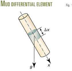
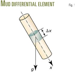
Fig. 1 shows a differential element of drilling mud. Equation 3 comes from the mass conservation law. The definition of bulk modulus yields Equation 4, and Equation 5 expresses the relative rate of element length change.
For the differential element of fluid, the relative rate of cross section change relates to the elasticity and supporting condition of the pipe. To determine how the pipe is fixed, three different types of constraints are as follows:
- The pipe anchors at the top only.
- No axial force applies to the pipe.
- The entire pipe is fixed, with no longitudinal strain allowed.
According to Hooke's law, the above constraints yield Equation 6 (Fig. 2). Equations 7 and 8 give the pipe bulk modulus of elasticity for thin and thick walled pipes, respectively.
Substituting Equations 4-6 into Equation 3 yields Equation 9. Equations 9 and 10 yield the continuity equation of one-dimensional unsteady flow in pipe (Equation 11).
The travel of a waterhammer wave along a pipe produces additional axial force, which will change both the pipe's diameter and length.
The industry frequently quotes A.R. Halliwell's 1963 work that describes the effects of wave velocity in an elastic pipe.12
Research published by E.B. Wylie and V.L. Streeter, however, has shown that only pipe-diameter change will influence wave velocity directly, and it includes ithe influence of pipe length change upon wave velocity.13
Axial stretch results in pipe volume increase, which will last long enough to change fluid density and reduce wave velocity and pressure.
On the other hand, axial stretch drags the fluid along, accelerating the process of fluid supply to the differential element, which tends to increase wave velocity and pressure. These two effects cancel each other exactly.
Drill pipe belongs to thick-walled pipe category. Equation 10 gives the mud-pulse propagation velocity and depends on mud density and compressibility, and on the drill pipe characteristics, but only applies to single-phase fluid.
Multiphase model
Drilling mud is a multiphase fluid, often containing clay, formation cuttings of various sizes, barite, and free gas mixed with water or oil, all affecting bulk modulus. The mud-pulse velocity relates closely to the apparent bulk modulus of the system.
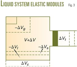
Fig. 3 presents a physical model that is useful for calculating the system's bulk modulus.14 The container, filled with liquids, solids, and free gas, has a piston at the right that applies pressure. Equations 12 and 13 determine the total volume and density of the mixture.
If the piston moves left by the volume ΔVt, it increases the pressure, Δp. At the same time, the volumes of the liquids, free gas, and solids compress by the amounts ΔVt, ΔVg, and ΔVs, and that of the container expands by ΔVp. Equation 14 calculates the apparent bulk volume change.
Equation 15 determines the compressibility of the system based on Equation 14 and the definition of bulk modulus. Consequently, Substituting Equations 13 and 15 into the definition of wave velocity yields Equation 16, which will apply to the actual drilling mud as multiphase fluid.
Analysis results
Equation 16 shows that the mud-pulse propagation velocity relates to many parameters, but in regular drilling operations, it mainly depends on the mud components and properties.15
Following is the input data for several examples covering mud-pulse velocity calculations involving free gas and solids:
- Drill pipe: D = 108.6 mm, e = 9.2 mm, λ = 0.3, Kρ = 2.1 3 105 MPa.
- Environment parameter: p = 30 MPa, T = 70° C.
- Solid phase: ρs = 2,660 kg/cu m, Ks = 1.62 3 104 MPa.
- Liquid phase: ρl = 1,000 kg/cu m, Kl = 2.04 3 103 MPa (Water-base mud).
- Liquid phase: ρl = 870 kg/cu m, Kl = 1.35 3 103 MPa (Oil-base mud).
- Gas phase: ρg = 0.9 kg/cu m (standard state), m = 1.2.
- Constraints: The drillbit is on bottom.
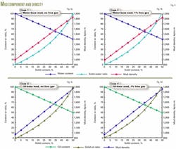
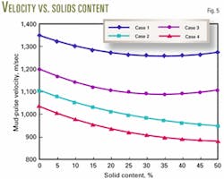
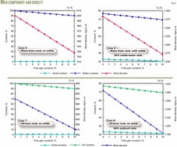
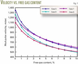
The authors provide eight examples of drilling mud calculations to simulate mud-pulse velocities. Figs. 4a-4d and 6a-6d show the mud types, components, and calculated densities. Figs. 5 and 7 show the mud-pulse velocities, calculated from Equation 16 and the input data above.
The research has led the authors to conclude:
- Mud-pulse velocity decreases as mud density increases.
- Mud-pulse velocity increases as the system's apparent bulk modulus increases.
- Solids content and free-gas content influence mud density and compressibility, respectively.
- The magnitude of mud-pulse velocity change in multiphase mud depends, quantitatively, on the corresponding change in mud density and compressibility.
- Mud-pulse velocity is particularly sensitive to free-gas content.
- Mud-pulse velocity in water-base mud is generally higher than that in oil-base mud, under the same conditions.
With the multiphase model proposed, engineers can easily simulate mud-pulse velocities of drilling mud that contains various amounts of solids and free gas.
References
- Desbrandes, R., "Status Report: MWD Technology, Part 1-Data Acquisition and Downhole Recording and Processing," Petroleum Engineer International, September 1988, p. 27.
- Poli, S., Donati, F., Oppelt, J., and Ragnitz, D., "Advanced Tools for Advanced Wells: Rotary Closed Loop Drilling System-Results of Prototype Field Testing," SPE paper No. 36884, 1996.
- McDonald, W.J., "MWD: State of the Art-1, MWD Looks Best for Directional Work and Drilling Efficiency," OGJ, Mar. 27, 1978, pp. 141-47.
- McDonald, W.J., "MWD: State of the Art-2, Four different systems used for MWD," OGJ, Apr. 3, 1978, pp. 115-24.
- Liu, X., and Su, Y., "Scheme Design of Downward Signaling System," Acta Petrolei Sinica, Beijing, Vol. 21, No. 6, 2000, p. 88.
- Arps, J.J., "Continuous Logging While Drilling-A Practical Reality," SPE paper No. 710, SPE Annual Fall Meeting, New Orleans, Oct. 6-9, 1963.
- Arps, J.J. and Arps, J.L., "The Subsurface Telemetry Problem-A Practical Solution," Journal of Petroleum Technology, May 1964, pp. 487-93.
- Spinner, T.G. and Stone, F.A., "Mud Pulse Logging While Drilling System Design, Development, and Demonstration," International Association of Drilling Contractors Drilling Technical Conference, Houston, Mar. 6-9, 1978, pp. 313-27.
- Desbrandes, R., Bourgoyne, A.T., Jr., and Carter, J.A., "MWD Transmission Data Rates Can be Optimized," Petroleum Engineer International, June 1987, p. 46.
- Desbrandes, R., "Status Report: MWD Technology, Part 2-Data Transmission," Petroleum Engineer International, October 1988, p. 48.
- Desbrandes, R., and Bourgoyne, A.T., Jr., "MWD Monitoring of Gas Kicks Ensures Safer Drilling," Petroleum Engineer International, July 1987, p. 43.
- Halliwell, A.R., "Velocity of Waterhammer Wave in an Elastic Pipe, " American Society of Civil Engineers proceedings, 1963, Vol. 89, p. 1.
- Wylie, E.B. and Streeter, V.L., Fluid transients, New York: McGraw-Hill Book Co., 1978.
- Liu, X., and Su, Y., "Study on Transmission Velocity of Mud Pulse Signal," Petroleum Drilling Techiques, Beijing, Vol. 28, No. 5, 2000, p. 24.
- Liu, X., Su, Y., and Cen, Z., "Analysis of Influence Factors on Drilling Mud Pulse Transmission Speed," Oil Drilling & Production Technology, Beijing, Vol. 21, No. 5, 1999, p. 1.
The authors
Zaihong Shi is reading for her PhD at the Institute of Mechanics of the Chinese Academy of Sciences in China. She received her BS and MS in petroleum engineering from Daqing Petroleum Institute. Her professional experience includes work as an associate professor at Daqing Petroleum Institute and Tsinghua University.
Xiushan Liu is a professor at Sinopec Corp.'s Exploration & Production Research Institute, a visiting professor at CNPC's Key Laboratory of Drilling Engineering, and a part-time professor at Daqing Petroleum Institute in China. He has a BS and an MS from Daqing Petroleum Institute and a PhD from Research Institute of Petroleum Exploration & Development of CNPC, all in petroleum engineering.
