New FPSO design produces LNG from offshore sources
This article is the fourth in a series that began in the Aug. 12 issue.
Merlin Production Inc., in cooperation with Costain Oil, Gas & Process Ltd. and Moss Maritime AS, has demonstrated that an economically viable floating LNG plant can be designed, built, and successfully operated.
The process selection procedure focused on an inherently safe design that uses well-proven equipment and LNG plant design practices. Formal safety assessments were used to underwrite all aspects of the design work, particularly plant layout.
The design process considered plant capacities between 1.2 and 3.5 million tonnes/year (tpy). The liquefaction process offers high flexibility to feed-gas conditions, high reliability, and is as inherently safe as an onshore LNG plant.
The design's central aim was to select the best LNG production technology and use well proven, low-capital-cost equipment. The design also considered and resolved other major technical challenges, including:
- Offshore LNG transfer.
- Relative movement between the floating, production, storage, and offloading (FPSO) plant and LNG carrier.
- Offshore LNG storage.
- Manpower requirements.
- Process plant maintenance.
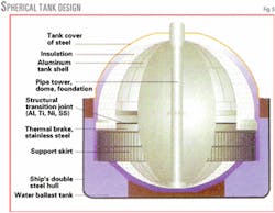
The companies also developed a proprietary design for an offshore floating storage and regasification unit (FSRU) based on the same hull and LNG tank configuration (Fig. 1).
Offshore LNG
Offshore LNG production has gained interest mainly in the US, which is now viewed as a primary growth area for LNG along with India and China.1
Increased natural gas demand for power generation is a major driver of LNG trade.
This coincides with technical advances and reduced project costs that make offshore LNG highly attractive as a "swing" supply source for natural gas.
The widespread use of floating vessels for oil and gas production shows that many aspects of the technology can be applied to offshore LNG production.
The LNG spot market and environmental pressures to reduce flaring during associated gas production have improved commercial viability even further.
Offshore LNG avoids major infrastructure costs associated with onshore baseload LNG projects such as offshore platforms, harbor, jetty, and site preparation. Avoiding these costs can significantly lower LNG production costs.
LNG production economics must be compared to the costs of pipelining gas. LNG is cheaper to develop many remote gas fields, especially because floating LNG facilities can easily move to new fields as current ones decline. LNG may also be stored to meet specific gas demand patterns.
LNG FPSO design philosophy
The selected LNG production technology should be:
- Well-proven.
- Inherently safe.
- Reliable (with redundancy).
- Simple.
- Of minimal equipment count.
- Modular.
- Easy to maintain.
Marine design basis
The vessel is a turret-moored floating unit designed to include a complete processing facility for liquefying and storing natural gas and condensate. Subsea pipelines connected to the mooring system by flexible riser lines supply feed gas to the vessel.
An external, single-point mooring system, based on passive operation with thruster assistance for heading control only, keeps the vessel in position.
The vessel was designed for the moderate environment of Northwest Australia. This environmental design basis incorporates the potential for deployment in other operational areas.
The vessel has a design life of 40 years and can last 20 years before first dry-docking.
Offloading occurs via side-by-side transfer through marine off-loading arms.
The hull has a similar construction to seagoing LNG tankers with cargo storage protected by double sides and a double bottom. The vessel is divided into four major category areas:
- The accommodation house with helicopter deck and utility service equipment. Thrusters are located aft.
- Two spherical LNG storage tanks partially protruding through the main deck.
- Process plant with condensate storage tanks, main power systems, main utility systems, and offloading station.
- Flare tower, mooring installation, storage space, etc.
The LNG is stored in spherical cargo tanks. Integral tanks are allocated for water ballast and arranged to maintain satisfactory trim regardless of the amount of LNG and condensate in the storage tanks.
The overall vessel shape design keeps movements and accelerations to a minimum and provides for maximum flat-of-side shell for proper tanker mooring.
LNG storage capacity is 181,800 cu m at 2 163° C. and the condensate storage capacity is 50,000 cu m.
Total dead weight including cargo, consumables, and stores is about 190,000 tonnes, including about 18,000 tonnes of ballast for trimming purposes.
Process plant design basis
Design and engineering studies considered natural gas flow rates between 200 and 450 MMscfd. The latter equates to an LNG production rate of approximately 3 million tonnes/year (tpy) based on 350 days/year of operations.
All LNG project costs increase as the need for acid-gas removal, NGL extraction, and nitrogen removal increases. Plant cost also increases with lower feed-gas pressure and higher ambient temperature due to increased power consumption.
Optimizing an onshore plant for specific feed-gas conditions can reduce plant cost. Offshore plant design, however, must be robust and flexible to changes in feed-gas conditions; the process design philosophy is different compared to an onshore plant that handles a specific, well-characterized feed gas.
The offshore LNG plant can remove up to 4 mole % CO2 from the feed gas and has feed-gas booster compression. Because the feed gas can have a high content of heavier hydrocarbons, condensate removal and stabilization are required to remove potentially freezable components and meet LNG product specifications.
The design assumes that the feed-gas nitrogen level is less than about 1.5 mole %; nitrogen removal is not needed.
Previous work
Life-cycle assessment for offshore liquefaction of natural gas includes the same process-design issues as a land-based plant; safety is paramount. Some recent design studies have considered mixed-refrigerant cycle technologies including the propane-precooled cycle normally used on baseload LNG projects and the single-stage refrigeration cycle.2
For offshore liquefaction, however, the criteria for technology selection differ substantially from those of onshore facilities. Because capital cost is only a fraction of total project cost, technology selection and process design must focus on overall project economics.
If all aspects of the process and plant design are based on an FPSO plant, this leads to an interesting conclusion regarding the best choice of liquefaction technology. The first reported work on offshore liquefaction of natural gas 20 years ago concluded that the most appropriate technology was a nitrogen-expander refrigeration cycle with precooling by mechanical refrigeration and liquefaction in aluminum plate-fin heat exchangers.3 LNG peak-shaving applications extensively used a similar technology.
Costain and Foster Wheeler Petroleum Development Ltd. further developed the process technology. In 1989, Costain developed a double-expander cycle design for the Pandora field, offshore Papua New Guinea, in conjunction with Three Quays Marine Services Ltd.
BHP Ltd. and Linde AG proposed the use of a double-nitrogen expander cycle to develop the Bayu-Undan field in the Timor Sea.4 5 Similar technology has recently been recommended for smaller plant capacities by the European Union-funded Project Azure.6 7
Selection criteria
To select the most appropriate refrigeration cycle, one must compare the options with these criteria:
- Safety. Minimum fire hazard based on inherently safe design and minimal flaring.
- Plot space.
- Sensitivity to vessel movement.
- Flexibility to handle different feed-gas conditions.
- Ease of start-up and shutdown.
- Simplicity of operation and ease of maintenance.
- Energy efficiency.
- Capital cost.
One should only consider well-proven, conventional processes and equipment.
Alternative refrigeration cycles
Three different refrigeration technologies were considered: cascade, mixed refrigerant, and expander refrigeration.
Cascade
Among onshore baseload LNG facilities, only the Atlantic LNG Co. plant, Point Fortin, Trinidad, uses a cascade cycle. Two trains of propane, ethylene, and methane systems provide refrigeration. Each system having a refrigerant compressor makes the plant machinery intensive.
Specific power is low but the plant is relatively complex and has many pieces of equipment. Each main refrigerant requires its own storage, which increases plot space. The many pieces of equipment and large plot space make this cycle uneconomical for offshore applications.
Mixed refrigerant
Costain assessed the mixed-refrigerant technology for offshore liquefaction based on single mixed-refrigerant and dual mixed-refrigerant cycles.2 6 8-10 Dual mixed refrigerant has a lower specific power but is more complex.
Shell International Exploration & Production concluded that the single mixed refrigerant is suitable for smaller capacities of around 2 million tpy of LNG and the dual mixed-refrigerant cycle is suitable for capacities up to, and potentially more than, 4 million tpy.10
The dual mixed-refrigerant cycle minimizes hydrocarbon inventories compared to the single mixed-refrigerant cycle and the Air Products & Chemicals Inc. propane precooled cycle normally used onshore.
Dual mixed refrigerant also has lower flaring rates in the event of compressor trip and refrigerant blowoff. All mixed-refrigerant cycles, however, require storage of flammable hydrocarbons. This presents a significant safety challenge and requires a significant amount of deck space.
All cryogenic plants need good distribution of two-phase streams into the heat exchangers, particularly mixed-refrigerant cycles. Lack of good distribution can result in lower production capacity. Vessel movement can make good distribution difficult to achieve; this can limit the use of mixed-refrigerant technology to calm seas only.11
Mixed-refrigerant plants are sensitive to changes in feed-gas conditions because they rely on small temperature differences between the composite cooling and warming streams to give reasonable process efficiency.
Onshore operators have time to optimize plant performance due to long plant run times. Offshore, the opposite can be true. Refrigerant composition must be adapted for different feed-gas conditions, which makes performance optimization difficult because the vessel moves to different sites.
Dual mixed-refrigerant technology gives improved operability vs. single mixed-refrigerant cycles but is expensive for all but the largest facilities.
Mixed-refrigerant plants take longer to start up and stabilize than plants using other refrigerant cycles because precise refrigerant blending is needed. This is a significant consideration in an environment where frequent start-ups and shutdowns are expected.
Expander
Turboexpander refrigeration cycles are well proven for cryogenic liquefaction, including LNG peak shaving and large-scale industrial gas liquefiers.
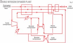
Compression and work-expansion of a suitable fluid, typically nitrogen, generates the necessary refrigeration. Cycle gas is boosted in the brake-end of the expander.
If only one stage of work-expansion is used, then power consumption is excessive and only justifiable for small plant capacities. Subsequent designs have concentrated on the use of a second expander.
Fig. 2 shows the basic process flowsheet. Both expanders can operate with the same pressure ratio at different temperatures, or the cold-end expander can operate over a much larger pressure ratio. The two machines use a common skid.
Because two expanders enable cooling and condensing of natural gas at small temperature differences, heat exchanger size increases, but specific power drops.
Mechanical refrigeration based on propane can reduce power consumption by cooling the feed gas and chilling the cooling water, which reduces the cycle compressor discharge temperature. Propane, however, introduces the need for flammable hydrocarbon storage. A "low ozone depletion" refrigerant represents a more appropriate choice than propane.
Increased complexity, reduced overall reliability, and the need for refrigerant storage are disadvantages for precooling.
Nitrogen as a cycle fluid is inherently safe. Nitrogen prevents the storage of hazardous hydrocarbons adjacent to, or within, the processing plant and no hydrocarbon flaring occurs if the refrigerant compressor trips.
The expander cycle is simple and has fewer equipment items than alternative refrigeration cycles. This results in reduced plot space and facilitates modularization. Expanders are reliable on nitrogen duty and maintenance requirements are minimal.
Because nitrogen is a gas throughout the refrigeration cycle, distribution in the heat exchangers is not a concern. Plant performance is less sensitive to vessel movement.
The nitrogen expander design can handle different feed-gas conditions and requires minimal operator intervention. Specific temperature control is not as important as with mixed-refrigerant cycles and the process is inherently more stable and robust.
The nitrogen design can quickly shut down in a safe and controlled manner; a plant can start up from a cold condition in less than 1 hr, whereas a mixed refrigerant plant may require many hours to reach steady state.
Technology selection
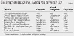
Table 1 summarizes the key selection criteria for the offshore LNG plant.
The technology in this LNG FPSO design is the double-nitrogen expander cycle. The use of two expanders avoids the need for precooling by mechanical refrigeration with distinct benefits in terms of reliability, space, and avoidance of refrigerant storage.
The double-nitrogen expander cycle requires more power than more complex cycles but the simplicity of the process makes it safer and less expensive.
Plant features
We designed the FPSO LNG plant for power generation, process cooling, ancillary utilities, and effluent minimization, taking into account space constraints.
Power generation
Process simulation and optimization work included:
- Assessing compressor and expander efficiency based on supplier quotations.
- Selecting the nitrogen cycle pressure.
- Balancing heat-exchanger capacity against power consumption.
Power consumption less than 0.5 kw-hr/kg is feasible, but we used a wider margin for good operability and control. LNG plant facilities are self-sufficient and there is minimal interface with the vessel support system except where major cost savings are feasible.
Up to six gas turbine generator sets for a 3 million-tpy plant supply electricity to the plant and vessel. These generate over 200 Mw of electricity. The nitrogen cycle compressors, which are driven by synchronous electric motors, use most of the electricity.
The gas turbine fuel requirement is equivalent to about 12% of the total natural gas feed rate. Gas turbine capacity is fully used, and this essentially sets LNG production capacity and plant equipment sizing.
The preferred generators are aero-derivative gas turbines. Compared to heavy-duty industrial gas turbines, aero-derivatives are appropriate for offshore use due to:
- High reliability.
- High efficiency.
- Small footprint.
- Low weight.
- Ease of installation and maintenance.
The choice of gas turbine generator establishes the deck size and layout and can have a significant impact on project cost. Larger generators take up more space and weight for a given plant capacity.
We selected General Electric LM-6000 turbines based on previous experience, specific evaluations, and a comparison of reliability and efficiency with other machines.
Waste-heat recovery is included only to meet process-heating duties. There is little scope for extensive thermal integration between the liquefaction plant and gas turbines, and waste-heat recovery requires excessive plot space.
We considered using absorption refrigeration, based on waste heat, for feed gas and cooling-water chilling. This concept may have merit depending on the specific project.
Process cooling
Air cooling requires a prohibitive amount of deck space.
Seawater cooling is conventional in offshore processing. The seawater cooling circuit can be either an open-loop or closed-loop system.
In the former, seawater is drawn in, pumped directly through the process heat exchangers and discharged back to the sea. In the closed-loop system, process- grade cooling water is pumped around a closed loop, with heat rejected via a cooling water-seawater heat exchanger.
The open loop circuit offers two advantages:
- Less equipment and less space.
- It can cool the nitrogen refrigerant to a lower temperature, thus improving process efficiency by typically 5%.
A drawback of the open loop is that expensive materials are required for all seawater service heat exchangers. Life-cycle evaluations showed titanium to be the material of choice due to its high resistance to oxidizing chlorides.
The heat exchangers in this design are aluminum plate-fin exchangers, which have these benefits:
- Close temperature approach and high thermal effectiveness.
- Large heat-transfer surface per unit volume.
- Low weight.
- Heat can be exchanged between several streams in one unit.
Aluminum is the material of choice due to its high strength at low temperatures, high thermal conductivity, ease of fabrication, and low cost. The effect of vessel motion on liquefaction performance is minimized due to the multiple pass configuration.
Nitrogen
During normal operations, make-up nitrogen is needed due to leaks from machinery seals and for continuous purging of the cold box enclosures that house the aluminum exchangers.
A semipermeable membrane unit or pressure-swing adsorption with a maximum oxygen content of 2% generates the nitrogen. The instrument air system supplies the required compressed air.
Dry gas seals on the compressor and expanders minimize nitrogen losses. Active magnetic bearings on the expanders can help avoid nitrogen loss and reduce expander skid size and weight.
Process heating
The molecular-sieve pretreatment system, acid-gas removal system, and condensate stabilization require process heating. Hot oil is preferred to steam, based on thermal efficiency, ease of operation, and overall plot space.
There is no direct-fired equipment on the process plant because it would constitute an unacceptable safety and operational hazard.
Effluent minimization
The acid-gas removal system produces low-pressure gas, rich in CO2 with small amounts of light hydrocarbons. This is vented at a safe height near the acid-gas removal system area.
Turbine exhaust gas is predominantly nitrogen, CO2, and water, with small amounts of CO and trace NOx and SOx.
During molecular sieve regeneration, oily water is produced. This is treated with hydrocyclones so that the clean water, which contains about 20-30 ppmv of hydrocarbon, can be discharged to sea.
There is no flaring under normal operating conditions, other than a nominal purge flow. The nitrogen cycle ensures there is no major hydrocarbon flaring, especially if a high-integrity instrument protective system is used at the plant inlet.
Modularization
Nitrogen cycle technology lends itself to modular design and fabrication, due to equipment size and few pieces of equipment.12
The plant has either two or four trains, based on permissible module and equipment size and plant capacity. Multiple trains mean:
- Operation can continue in case one train shuts down; high overall system reliability is maintained.
- Equipment size ensures that the number of suppliers is commercially acceptable.
- Parallel operation enables the plant to be laid out symmetrically on either side of the vessel, which maintains vessel stability and ensures minimal effects due to vessel movement.
- Turndown increases.
Module limits are based on what can be fabricated either locally at shipyards or locally at a port for transporting to the shipyard. Machines arrive on skids fully piped, wired, and tested; this practice is extended for all equipment as is practical.
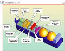
Fig. 3 shows the plant layout for a nominal 2 million tpy LNG FPSO.
Modular topside construction at an established fabrication shop leads to high-quality work and lower overall capital cost compared to site work, especially in areas of high labor rates. Direct costs are lower due to better supervision in the fabrication shop and work can continue irrespective of weather. A smaller construction labor force, less rework, and a shorter project schedule reduces indirect costs.
Vessel and topside modules can be fabricated in parallel, which should reduce the time to full LNG production compared with a similar capacity onshore plant.
Other challenges
Offshore LNG plants face other challenges including cargo transfer, sea motions, limited manpower supply, LNG containment, and safety issues.
Cargo transfer
Offloading LNG from offshore-based operations requires bulk LNG carriers to approach and berth alongside the floating structure. Although similar activities frequently occur with FPSO operations, this is a major hazard concern for offshore operation.
In accordance with best practices, the offshore industry has developed LNG transfer guidelines for ship-to-ship cargo transfer operations.13
Det Norske Veritas (DNV) conducted a review of the safety and operational requirements associated with the design, construction, and maintenance of an FSRU.14 The review includes offshore LNG cargo-transfer operations.
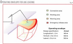
Based on the design and operation information (Fig. 4), DNV provided a provisional approval for the LNG FSRU design, assuming that the FSRU is designed, constructed, maintained, and operated according to customary practice for the offshore industry.
Relative motions
Offloading dynamics can also involve relative motions between the floating structure and ship that exceed those found for onshore-based activities where bulk carrier loading is performed.
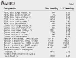
Table 2 shows the results of anticipated vessel motions for the LNG FPSO. Wave data are those of the vessel design criteria of Northwest Australia.
Results are based on a 3-hr storm. The motions are maximum amplitudes and tension forces are maximum values including mean value.
Tensions in the mooring lines are acceptable. Tension corresponds to elongation of the nylon rope within 11%. The maximum reaction force in the fenders corresponds to a maximum compression within 12%.
We calculated relative motion between a point on the LNG FPSO deck (at the loading arms) and a point on the LNG carrier at the same longitudinal position and level. Results indicate that relative motion is well within the operational envelope of a standard LNG loading arm.
We also calculated relative motions between points at deck level on the two hulls to check on possible contact due to roll motions. With the vessels about 4 m apart, there should be no contact between the two hulls.
Manpower requirements
Workforce population estimates for operating and maintaining an offshore LNG production facility are about 250 employees. This concerned us in the event of an emergency evacuation due to a major accident.
A detailed analysis of offshore manning requirements for the LNG FPSO shows that the unit will require at least 86 persons, with an accommodation capacity of 100.
The operator should schedule facility maintenance to ensure that major repairs, such as those performed on aero-derivative gas turbines, are performed off site.
Periods of planned maintenance, especially those involving planned shutdowns, will typically have additional maintenance personnel on the vessel. During those periods, accommodation capacity will still be adequate. All nonessential personnel, such as painters, oilers, cargo handlers, and loading supervisors will return to shore.
LNG containment systems
Similar to onshore LNG operations, the offshore design stores significant amounts of LNG in dedicated storage tanks. A catastrophic tank failure and subsequent discharge of LNG into the sea, followed by a rapid phase transition can cause serious structural damage to the offshore facility, with possible stability loss.
Merlin performed research on the main tank design criteria, specifically for an LNG FPSO. The main issues are:
- Insulation.
- Inspection.
- Sloshing.
- Cargo tank leakage.
- Ballast tank leakage.
- Time for repair.
- Collision resistance.
- Service record.
- Rollover prevention.
One of the most important aspects of the LNG FPSO and FSRU designs is the size of the LNG storage tanks. The LNG storage system is crucial to the long-term success of an offshore LNG project. Results of design work with 90,000-cu m tanks confirmed that these tank sizes are achievable given that:
- Scantling is based on environmental conditions in Northwest Australia.
- Global analysis, which proves performance for areas outside the equator area, shows that the stress level is within the requirements set by DNV rules and IMO's International Gas Carrier Code (see related article, p. 64.
- Local analysis results show that the design of the equator area also fulfills these requirements.
- Analyses performed with analytical software programs confirm that the scantling layout has the necessary buckling resistance and the vertical stiffeners have the necessary stiffness properties.
- Scantling is well within practical and acceptable dimensions and suited for fabrication by shipyards familiar with this type of construction.
null
Safety assessment
Safety is important on LNG facilities. Any viable offshore development must demonstrate equivalent or superior performance compared to an onshore plant.
At the conceptual design stage, safety assessments from similar projects performed by Costain were used to determine plant layout and the optimal vessel-process interfaces.
Merlin engaged DNV to conduct a review of all technical requirements related to safety and operational issues for the LNG offshore facilities.15 The report, combined with research and design work, addressed historical barriers to offshore LNG facilities. The assessment was based on a qualitative review, supported by quantitative consequence analysis, for these typical accident types:
- LNG release.
- Ship collisions.
- Dropped objects.
- Helicopter accidents.
- Ballast failures.
- Fire and explosions.
The DNV report showed that the LNG FPSO met or exceeded current safety criteria. A more-detailed safety case is required for a specific project, which could conclude that the risk levels were somewhat higher. Detailed safety issues should be fully resolved during detailed engineering.
References
- True, W.R., "LNG imports needed to meet growing US gas supply deficit," OGJ, Oct. 2, 2000, p. 28.
- Price, B.C., and Mortko, R.A., "Development of mid-scale and floating LNG facilities," presented to the GasTech 98 conference, Dubai, Nov. 29-Dec. 2, 1998.
- Kennett, A.J., Limb, D.I., and Czarnecki, B.A., "Offshore liquefaction of associated gas - a suitable process for the North Sea," presented to the Offshore Technology Conference, Houston, May 1981.
- Dubar, C., Forcey, T., Humphreys, V., and Schmidt, H., "A Competitive Offshore LNG Scheme Utilising a Gravity Base Structure and Improved Nitrogen Cycle Process," presented to the LNG12 conference, Perth, Australia, May 4-7, 1998.
- Cottrill, A., "An offshore LNG first for Undan/Bayu," Offshore Engineer, April 1997, p. 21.
- Sheffield, J.A., and Mayer, M., "The Challenge of Floating LNG Facilities," presented to the European GPA Spring Meeting, Norwich, UK, May 16-18, 2001.
- True, W.R., "Study says floating liquefaction plants are viable," OGJ, Apr. 9, 2001, p.62.
- Naklie, M., "Mobil's Floating LNG Plant," presented to the LNG12 conference, Perth, Australia, May 4-7, 1998.
- Johnsen, R.J., and Christiansen, P., "LNG Production on Floating Platforms," presented to GasTech 98, Dubai, Nov. 29-Dec. 2, 1998.
- Bliault, A., "Shell floating LNG plant, technology ready for project development," Offshore, May 2001, p.102.
- Pekdemir, T., Dept. of Mechanical and Chemical Engineering, Heriot-Watt University, Edinburgh, UK, private communication, July 2001.
- Vink, K.J., and Nagel voort, R.K., "Comparison of Baseload Liquefaction Processes," presented to the LNG12 conference, Perth, Australia, May 4-7, 1998.
- "The FSRU Cargo Transfer Guidelines," Merlin Production Inc., June 2001.
- "Merlin Production FSRU, Review of Technical Requirements," DNV Technical Report No. 2001-440-3521, Det Norske Veritas, Norway, July 2001.
- "Risk Assessment of an LNG FPSO", DNV Technical Report No. 2000-3389, Merlin Production-Moss Maritime, September 2000.
The author
Adrian J. Finn is technology development manager with Costain Oil, Gas & Process Ltd., Manchester, UK. He has spent 19 years with Costain mainly as a process engineer on gas processing projects. He holds a BScTech in chemical engineering and fuel technology from Sheffield University and an MS from Leeds University (both UK). Finn is a fellow of the Institution of Chemical Engineers and is a chartered engineer in the UK.


