Water-injected flare tips reduce radiated heat, noise
Several case studies illustrate the benefits of an ultra-low radiation, water-injected, sonic flare tip. This equipment can:
- Lower costs for new facilities by reducing structural requirements.
- Reduce costs for modifying existing structures.
- Lower maintenance costs because of a longer tip life.
- Reduce unplanned shutdowns because of tip failures.
- Lower installation costs by using a helicopter or nominal lifting equipment.
The modular design of these flare tips provide flexibility to accommodate varying flaring rates by providing spare nozzles for additional sonic tips or permitting nozzles to be sealed with blind flanges as tips are removed.
Offshore flares
Offshore facilities employ flaring systems to dispose of waste gas in a safe and environmentally conscious manner. To protect personnel and equipment during both continuous and emergency flaring scenarios, engineers design flares that limit radiation and noise while maintaining profitability and accommodating varying production levels.
Operators of new offshore facilities control radiation and noise by installing a flare tip at a sufficient distance from production facilities. Radiation from the flare tip determines the distance required. Less distance equates to a lower construction expense.
Available options include:
- Remote platform supporting a boom or tower and connected to the production facilities by a bridge-supported pipe or flexible hose.
- Floating flare secured to the seabed and connected to the production facility by a flexible hose.
- Boom cantilevered from the production facility structure.
- Vertical flare tower mounted on the production facility structure.
Existing offshore facilities may experience unacceptable levels of radiated heat, noise, and light if flared gas rates increase. The rate increases might stem from higher than estimated GORs, greater oil production rates, additional wells, and debottlenecking.
In these cases, one might mitigate flare-related problems by:
- Installing a high-pressure flaring system.
- Modifying the existing flare tip.
- Extending or replacing the flare boom or tower.
- Installing a floating flare.
- Connecting the gas to a pipeline.
- Installing a new platform, bridge, and flare tower or boom.
New construction, engineering, fabrication, and piping modifications with the corresponding shutdown time are often expensive.
Conventional flares
High-pressure flaring systems have been the most efficient solution for controlling emissions from new and existing facilities.
These flares use the energy associated with high-pressure gas to inspirate and mix large quantities of combustion air into the flames. The aerated flames are short and highly directional with low radiation.
Conventional high-pressure flare designs fall into the following three categories.
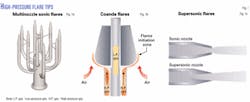
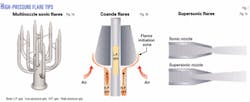
- High-efficiency multinozzle sonic flares (Fig. 1a) have an array of small diameter arms to separate the flow of flare gas to individual nozzles. Each arm is fitted with a convergent jet nozzle designed to discharge the gas at sonic velocity. Sonic flow inspirates and mixes large quantities of air into the column of gas creating an aerated, low-radiation flame.
- Coanda flares (Fig. 1b) employ the ‘Coanda effect’ to entrain and mix air into the flare gas stream. The flare ejects high-pressure gas radially from an annular slot at the base of a tulip-shaped Coanda profile. Instead of continuing horizontally, the gas adheres to the Coanda profile and is diverted at 90°, entraining large volumes of air in the process.Coanda flares are in either a fixed slot design, which exhibits hydraulics nearly identical to multipoint sonic flares, or a variable slot design, which modifies the hydraulics to produce nearly 100% turndown capability.On the variable-slot Coanda flare, one can adjust the flow area of the flare tip based on the actual operating pressure. This allows the flares to produce sonic flow conditions at a low flow rate. Radiation from a variable-slot Coanda flare remains low throughout the entire flow capacity range.
- Supersonic high-pressure, multinozzle flares (Fig. 1c) are relatively new to the industry. Their convergent-divergent nozzles create a supersonic gas flow that increases the air aspiration compared to conventional sonic nozzles.
Greater aspiration allows for an incremental decrease in the radiation from the flame. The nozzle design, however, decreases the turndown compared to conventional sonic designs.
New, high-volume offshore production platforms require a large flaring capacity; therefore, designers typically focus on the maximum emergency-flaring capacity.
Most high-pressure flare systems operate over a wide range of flow rates from purge to maximum. In many offshore locations, the allowable flare radiation is 150-300 btu/hr-sq ft at the base of the flare structure.
When gas production rates are higher than expected or the loss of a gas compressor occurs, high continuous flaring rates may create unsafe and uncomfortable conditions during normal platform operation and maintenance activities. Also solar radiation increases the total radiated heat during normal continuous flaring rates.
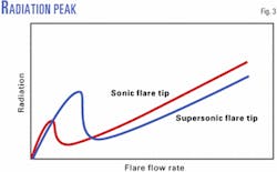
The low radiation properties of the flare are lost when one operates a high-pressure flare at subsonic flow conditions. The flames become directional with the wind. The subsonic flow creates a peak in the radiation produced by the flares during turndown. If the normal, continuous flaring rate is near the subsonic peak in radiation, the flare rates can often produce higher than expected radiation levels on the production deck, which may limit production.
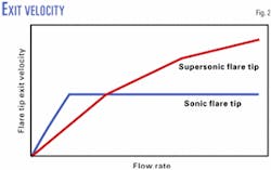
Supersonic nozzles are less efficient at subsonic flows. Because the exit area of the diverging nozzle is larger than the nozzle throat (Fig. 1c), a supersonic nozzle has lower exit velocity at turndown than a conventional sonic nozzle or Coanda tip (Fig. 2). This creates a higher corresponding peak in radiation that occurs in the subsonic flow region (Fig. 3). As a result, the supersonic flare design may produce high radiation levels and flame impingement of the flare body during turndown operating conditions.
Flare-tip longevity and smoke production are other major concerns when high-pressure flares are used in a turndown mode. A high-pressure flare tip operating at subsonic flow rates creates a low-velocity, lazy flame that often results in flame lick on the metal surfaces of the flare tip. The flame lick may produce smoke and excessive temperatures, causing fatigue and mechanical failure of the flare tip.
Restoring safe operation requires that the platform be shut down to access, repair, and replace the damaged flare tip.
The cost associated with lost production during an unscheduled shutdown in addition to the direct costs associated with flare tip replacement, lift equipment, rigging contractors, replacement flare tip, installation labor, etc., result in a need for a lower-cost alternative to control radiation and noise emissions.
Next-generation flares
Water-injected, high-efficiency, sonic flare tips allow for safe flare operations at increased oil and gas production rates. As shown by extensive testing and actual field performance, these flares also reduce emissions.
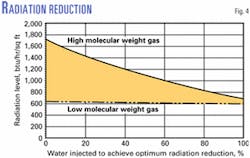
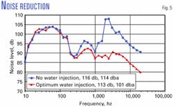
Water injection in particular improves high-pressure flare performance at or near turndown conditions. Under some conditions, measurements show a 50% radiation reduction and a 13 weighted decibel (dba) noise reduction (Figs. 4 and 5).
A water-injected flare retrofit can eliminate the need to increase the distance between the flare tip and personnel and production equipment required to meet acceptable radiation and noise limits.
Water injection improves flare operations by:
- Reducing radiated heat from the flame.
- Improving flame characteristics to lessen wind effects.
- Suppressing smoke.
- Decreasing noise levels.
The new tip compares in weight to conventional tips and may be mounted on an existing pipe flange, thereby minimizing modification expenses and costly downtime.
Many offshore platforms have existing seawater pumping capacity that can be tied into the flaring operations. Platform modifications may include only simple installation of booster pumps and piping for water delivery.
Caspian Sea example
A production platform in the Caspian Sea experienced unacceptable and continuous radiation on the deck as a result of high gas production. This radiation forced the operator to decrease the oil production rate.
The existing flare had a vertically mounted, high-efficiency, sonic flare tip. The tip was on a 20°, 165-ft long, angled flare boom. To reduce radiation, the flare engineers proposed that the operator retrofit the flare boom with a 45°, angled, water-injected flare tip.
To verify performance prior to installation, the engineers first tested the flare tip at a flare-testing facility. The high-capacity tests of the normal continuous-flare rates used a gas composition nearly identical to the actual field conditions.
Installed in 1999, the new flare-tip design lowered the noise by 10 dba and the radiation by 75% at the deck level during the normal continuous flaring rates.
The flare tip has operated continually since installation. The increased high-pressure flaring capacity on the platform allowed the operator to increase net oil production by more than 25%.
Off Africa example
An operator off Africa selected the water-injected flare technology as the best available design to control high radiation and noise levels that were creating unacceptable working conditions on the production deck of a facility.
Higher-than-anticipated gas-flow rates produced high radiation and noise, although the existing supersonic-design flare tip met the original design specifications.
The operator considered building a separate, remote flare platform, but due to the deep water, the only feasible conventional solution was the installation of a floating platform connected by a flare-header tendon at a $5-6 million cost.
The operator needed to find a flare modification for the high heat and humidity area that would allow a maximum, continuous flare radiation level less than 180 btu/hr-sq ft (500 btu/hr-sq ft total, including 320 btu/hr-sq ft solar radiation) at all personnel locations. The operator also sought to reduce noise to the lowest possible value.
The operator first had the water-injected flare tip tested at the flare engineers’ test facility under nearly identical, full-scale operating conditions, including gas composition and operating pressure. The tests showed emissions below required values.
Currently, the water-injected flare tip is being installed on the offshore platform.
Gulf of Mexico example
An operator in the US Gulf of Mexico recently retrofitted two supersonic design flare tips to allow increased capacity of an existing flare boom to accommodate a subsea tieback.
Although the supersonic flare tips performed well at high-flow design conditions, the normal continuous flow rates resulted in subsonic flow conditions. This low-flow operation produced large, lazy flames with excessive flame lick between the two adjacent high-pressure flare tips.
The harsh, normal operating conditions caused excessive overheating of the flare tips that led to fatigue and mechanical failure of the flare tip’s gas distribution arms. The rapid failure of the supersonic flare tip required unscheduled platform shutdowns and millions of dollars in lost production.
Following the second mechanical failure of the supersonic flare tip, the operator contacted the engineers of the water-injected technology to discuss possible design modifications. The water-injected flare tip proved the best alternative to meet the radiation and noise requirements and enhance overall mechanical design through improved turndown operation.
The water-injected design uses multiple, flanged nozzles on a common gas distribution manifold. This particular retrofit featured several extra blinded, flanged ports on the main manifold allowing for upgrades simply by adding additional sonic nozzles.
Modular design of the flare tip proved beneficial because the platform is also under expansion to accommodate future tiebacks.
The engineers designed the water-injected flare tip with an angled orientation to lower the maximum radiation and noise produced by the existing supersonic flare tips. The improvement in turndown operation and enhanced mechanical design also ensures flare-tip longevity.
To prevent the high cost of unscheduled platform shutdown, the operator had the new water-injected flare tips manufactured within 4 weeks and shipped to the platform for installation at the next scheduled turnaround.
The authors
Kevin Leary is manager of applications engineering at John Zink Co. LLC, Tulsa. He previously worked for Kaldair Inc. At John Zink, he coordinates and manages client technical and commercial proposals, production, systems process engineering, equipment selection and sizing, price estimation, and technical services. Leary has a BS in chemical engineering from Pennsylvania State University. He is a member of AIChE and ISA
Dennis Knott is a senior flare design engineer for John Zink Co. LLC, Tulsa. His responsibilities include system designs, product development and testing, and characterization of flare products. Knott has a BS in mechanical engineering technology from Oklahoma State University.
Raymond G. Thompson is a lead structural engineer for Mustang Engineering LP, Houston. He has more than 28 years of experience in the structural design of offshore oil and gas facilities and of refining and petrochemical projects. Thompson holds MS and BS degrees in civil engineering from Texas Tech University, Lubbock.
