Olefin producer uses shed decks to improve quench tower operations
Three intercooler water quench towers in the cracked gas compressor train of the Carmel Olefins Ltd., Haifa, Israel, plant had poor heat transfer. Temperature approaches between the quench water and overhead gas ranged from 6° C. to 12° C.
A major engineering contractor, in a debottleneck study, recommended replacing the sheds with packing to improve heat transfer and reduce the temperature approaches. Concerns about packing and distributor plugging by polymers, possible reflux flashing, high gas inlet velocities, and possible liquid-phase separation in the distributors provided incentives for avoiding packings.
When correctly designed and widely spaced, shed decks will surpass, or at least equal, the capacity of any packing. Shed decks' tolerance to plugging, liquid and gas maldistribution, and flashing of light material from the reflux is superior to that of packings. Their heat-transfer performance is not always far inferior to that of high-capacity packings.
Over the last decade, we have seen debottlenecks in which shed decks were replaced by packings. Many were successful, especially when the section was short or the initial shed deck design was inferior. In others, the benefits were marginal. There were a few debottlenecks in which packing introduced operating problems.
Field testing, coupled with a review of the shed deck design, helped us identify major deficiencies in Carmel's existing hardware. Double-pipe distributors dumped liquid into the towers' centers but left large peripheral regions unirrigated. Gas inlet velocities were too high to give good gas distribution. The shed decks themselves were too wide, which impeded gas-liquid contact. We concluded that correcting these deficiencies could reduce the high temperature approaches.
Modifications to the three towers included: replacing the double-pipe liquid distributors with spray distributors, improving gas distribution, and installing narrow shed decks. Subsequently, approaches between the overhead gas and quench temperatures decreased by a factor of two or more. Heat-transfer coefficients increased 55-120% and random packings could have effected only a minor further improvement.
The lesson learned is that good field testing, troubleshooting, and deficiency identification in an operating system are the keys for improving quench tower operations. Gross changes such as replacing sheds with packings may be excessively costly and nonoptimum and may also substitute an old problem with a new one.
Process description
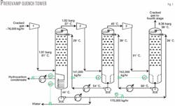
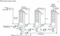
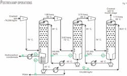
Pyrolysis furnace effluent is quenched and cooled before entering the cracked gas compressor. This five-stage centrifugal compressor (Fig. 1) compresses gas from 0.5 barg to 31 barg.
After each step, gas at about 90° C. enters a water quench tower, where it is cooled to about 40° C. by direct contact with circulating water. A quench tower follows each of the first three compression stages.
In each quench tower, circulating water enters the top. Each quench tower contains 12 rows of shed decks, nine sheds/row. The rows are spaced 700 mm apart, each row rotated 90° to the one below.
Shed decks provide the gas-liquid contact surface for direct-contact heat transfer. The quench towers' inside diameters are 2,850 mm, 2,650 mm, and 2,250 mm, diminishing at the higher stages. Each quench tower is equipped with a vane-type demister at the top gas outlet.
Liquid reaching the first-stage quench tower's bottom is circulating liquid plus condensate from the gas. Any condensed hydrocarbons decant from the water, cool down, and flow to the oil-water separator upstream of the first-stage suction. Remaining liquid is water, which is pumped and water cooled. It is then split into a circulating water stream, which is sent to the top of the third-stage quench tower, and the balance, which exits into the oil-water separator upstream of the first-stage suction.
Liquid collected at the bottom of the second and third-stage quench towers is circulating water plus condensed water and hydrocarbons. The unseparated liquid is pumped to the top of the next lower stage quench tower.
Bottom pumps on the second and third-stage quench towers do not operate at start-up because there is enough pressure difference between the stages to send liquid through the exchangers. These pumps are used when the exchangers foul and their pressure drops rise.
Operating history
The quench towers originally started up in 1979, with water circulating at close to the design flow rates. The towers successfully cooled the gas, but only to 6-12° C. above the entering quench water, which is above the expected approach.
Volumetric heat-transfer coefficients based on sensible heat transfer were about 30-50% less than we expected. With the quench water temperature reaching 37° C. in the summer, gas left the quench towers at 45-50° C. Higher gas temperatures increased compression loads on the cracked gas compressor and, consequently, its energy consumption.
Before 1995, the cracked gas compressor was not a bottleneck. The hot gas temperature increased energy consumption, but Carmel could tolerate the economic loss. In 1995, the plant was debottlenecked from 150,000 to 185,000 tonnes/year (tpy) ethylene production. At 185,000 tpy, the cracked gas compressor limited plant throughput.
Hot quench tower gas outlet temperatures bottlenecked the cracked gas compressor capacity in the summer.
During a brief shutdown for another revamp in 1996, Carmel inspected the quench towers. The pipe distributors spreading liquid to the shed decks were plugged. To prevent replugging, Carmel increased distributor hole size from 10 mm to about 12-13 mm.
The holes were large enough to alleviate plugging, yet small enough to generate pressure drops through the perforations, which are more than 10 times the pressure drop through the pipe, in accordance with good design practices for pipe distributors.1-3
After the 1996 shutdown, gas outlet temperatures did not decrease and the approach between gas temperatures and quench water did not improve. Distributor hole plugging, however, did not recur.
Packing debottleneck proposal
Carmel was considering increasing plant capacity from 185,000 (600 tonnes/day; tpd) to 300,000 tpy (900 tpd) ethylene production. A major engineering contractor performed a debottleneck study in 1996 that proposed replacing the shed decks with high-capacity random packings to lower the temperature approaches from 6-12° C. to less than 5° C.
This would ensure that, even with quench water at 37° C., the gas would leave the towers below 42° C. High-capacity packings could increase quench tower vapor-handling capacity.
The contractor specified large packing, with a specific surface area of 75 sq m/cu m, which coincides with 3.5-in. Pall rings and other modern proprietary packings. The specified bed height was about 1 m short of the shed decks. This space was for liquid distribution equipment. The contractor required a new packing distributor for each quench tower but left the specifications to the vendor.
We had concerns about packing in this service and, therefore, critically evaluated the packing proposal.
Packing benefits
Packing gives heat transfer benefits in quench towers. Pressure drop and capacity do not appreciably improve with packing.
Heat transfer
Heat-transfer coefficients in this plant are volumetric coefficients based on sensible heat exchange.
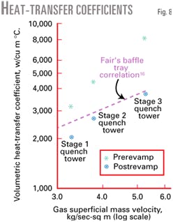
Operating data in Fig. 1 gave heat-transfer coefficients of 2,040, 2,650, and 3,730 W/cu m °C. for the first, second, and third quench towers, respectively, with the original shed decks. Heat-transfer coefficients that we back-calculated from engineering contractor design figures for the packing, scaled down from the 900-tpd debottleneck rate to the test 600-tpd production rate, were 50% greater than those measured with the existing shed decks.
Based on our test data with quench towers, packings should have even higher coefficients. Compared to the existing shed decks, packings should improve heat transfer 50-100%. The packings specified were large to maximize capacity. Smaller packings will improve heat transfer even further but at the expense of not maximizing future capacity.
Pressure drop
We do not have a good method for evaluating existing shed deck pressure drop. The pressure drop of well-designed shed decks at the test plant loads (600 tpd) is around 1.5-2 millibar/ row of decks. Twelve decks have a total pressure drop of 20 millibars.
The packing pressure drop, around 10 millibars, agrees with the number from the contractor. There is a 10-millibar pressure drop advantage for packings vs. sheds in each quench tower. This is a small and economically negligible benefit.
Packing vs. shed deck capacity
Packing capacity does not exceed shed deck capacity. While shed decks are not the most efficient heat-transfer devices, there are few alternative devices that match the capacity of well-designed and well-spaced shed decks.
A recent study4 applied data released by Fractionation Research Institute (FRI)5 to show that well-designed baffle trays with more than 44% open area often reach the system limit (ultimate capacity) when the tray spacing exceeds 600 mm. The settling velocity of liquid drops determines ultimate capacity, which is independent of tower internals.
In the Carmel quench towers, tray spacing is 700 mm, where well-designed baffle trays approach the ultimate capacity. The shed decks are a variation of baffle trays that split liquid into more curtains. Being ultimate-capacity limited means that no conventional device can exceed shed deck capacity.
The system limit study4 showed that large random packings, such as those specified for the packing debottleneck, also approach the system limit and will approach the shed decks' capacity. But nothing will exceed it; so, packings cannot exceed the capacity of 700-mm spaced shed desks.
Packing problems
In this service, packing often has potential problems with maldistribution (caused by flashing, plugging, and two-phase settling), and polymer buildup.
Distribution
Liquid to the packing must be well distributed for packings to perform effectively. Poor liquid distribution can cancel any benefits that the packing surface area may offer. Packings also require good gas distribution. Due to low pressure drop, packings are prone to gas maldistribution.2 6 7
A few vendors specify spray distributors for good packing performance. They normally specify gravity distributors and the occasional ladder-pipe pressure distributor. Spray distributors have inferior irrigation compared to gravity distributors. Packed towers generally do not use spray distributors because good irrigation is important.
Distribution quality with shed decks is less critical, and well-designed sprays are satisfactory. In this service, spray distributors are more reliable than gravity distributors.
Distribution difficulties
Three factors make liquid distribution to packing particularly difficult to achieve in intercooler quench towers.
- Flashing. Water used for quench comes from higher-pressure accumulators. Flashing may occur when the water is let down in pressure to the next tower. The weight of gas generated is small, but even this small quantity must be degassed before entering a gravity liquid distributor. Due to low gas density, even small quantities of gas generate large volumes. Gas in a liquid distributor is a prescription for poor distribution.6
We could not predict whether flashing would occur because the amount of condensed gasoline and the concentration of lights in the gasoline vary. Some simulation work could have been useful, but it may have only been as reliable as the assumptions. The conservative approach was to assume that flashing would occur.
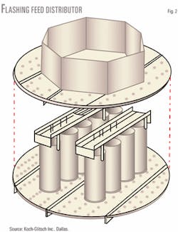
A gallery distributor (Fig. 2) overcomes this problem. In this two-plate distributor, the upper plate separates gas and the lower one distributes liquid. Designers routinely specify these distributors in amine regenerator towers in which rich amine from an absorber is let down into the regenerator, a similar operation to a quench tower.
- Plugging. The existing distributors experienced plugging in the 10-mm diameter holes. Larger holes (about 12-13 mm) mitigated plugging. Most commercial packing distributors, however, are the gravity type. These distributors have large residence times in the pans or troughs and lower liquid velocities, both of which can promote plugging.
When gravity distributors plug, liquid can build up to the top of the gas passages and then entrain in the gas to the compressor. This cannot happen in a system that has a pressure distributor. But it is a new problem introduced with tower repacking. Demisters can remove fine mist generated by a pressure distributor, but they are ineffective with massive entrainment generated when a gravity distributor overflows.
Special features in distributor design and thorough water filtration can circumvent the plugging problem. Both solutions require much cost and effort.
- Two-phase settling. Water quenches are mixed with gasoline, which will form two liquid phases that remain mixed in pipes and pipe distributors. These two liquid phases, however, can separate in troughs or pans of gravity distributors. When they do, only water will issue from the holes. Gasoline floats on the water and accumulates in the distributor. A slug of gasoline will eventually issue, upsetting the tower and compressor. Harrison discussed separating two liquid phases in gravity distributors.8
Special distributors can handle two liquid phases, but they are uncommon. They are not normally used with a gallery distributor. We have never seen a combination gallery, two liquid phase distributor.
A common practice is to separate gasoline from water before feeding it to the distributor. This coincided with the proposal by the engineering contractor. Water-gasoline separation is, therefore, necessary to ensure success of gravity distributors in quench towers. This would also solve the potential flashing problem, but it would not be cheap.
Polymer buildup
Polymer buildup is common in cracked gas compressor interstages. Carmel experienced fouling in the quench circuit heat exchangers and in the 10-mm distributor holes.
Polymer also plugs packing. Carmel routinely experiences polymer buildup in its process water stripper packings. Although online washes and antipolymerization inhibitors can mitigate or suppress polymer formation,9 10 they represent additional expenses, operating difficulties, and uncertainties.
With Carmel's quench tower overheads directly entering the compressor, liquid carryover from a plugged bed of packings can damage compressor internals. Fouling-resistant shed decks in the quench towers are a better way to ensure trouble-free operation. In more than 20 years of operation, Carmel never experienced shed deck fouling in any quench tower.
Packing pros and cons
The only justification for replacing the sheds by packings in Carmel's towers is to improve measured heat-transfer coefficients by 50-100%. There are no pressure drop or tower capacity benefits for packings vs. shed decks in Carmel's quench towers.
One problem exists with packings: To ensure good liquid distribution and no flashing, packing needs additional equipment to settle and decant gasoline from water collected in the second and third-stage quench towers. Packings are more sensitive to gas and liquid maldistribution, which requires expensive liquid and gas distribution equipment. Packing distributors, and the packing itself, are more prone to fouling and polymer formation. Distributor or packing plugging can lead to liquid entrainment that can damage compressors.
Packings are more troublesome than shed decks during abnormal operations. The larger packing surface area promotes corrosion during operation and fires during turnarounds. Packing supports and holddowns are easily dislodged during compressor surges and rapid depressurization.
Good design features can alleviate many of these concerns. They are expensive, however, especially liquid distribution, and gasoline settling and decanting equipment.
High costs and reliability issues of packings in this service gave Carmel an incentive to reconsider shed decks. Carmel wanted to identify deficiencies with existing shed deck design, and an improved design with shed decks that would significantly enhance heat-transfer coefficients.
Quench water distribution
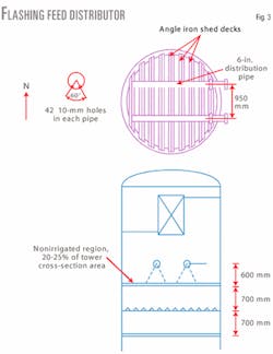
Fig. 3 shows the double-pipe distributor supplying liquid to shed decks. About half the quench is dumped along the tower east-west centerline. The other half is dumped along two narrow east-west chords, halfway between the east-west centerline and the north and south ends. The north and south ends and the regions under the pipes remain unirrigated. This is poor distribution.
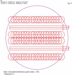
Fig. 4 shows the dry areas based on a distributor irrigation quality analysis using the Moore and Rukovena method.11 We and others strongly recommend this method for distributor analysis.2 6
We calculated a distributor quality index of 13%. According to Moore and Rukovena, a high-quality distributor has an index higher than 90% and an intermediate-quality distributor has an index of 75-90%. The distributor index of these double-pipe distributors falls into the extremely poor category.
While liquid distribution is less critical for shed decks than for packings, shed decks still require at least close to an intermediate distribution quality (index of 50-60%). Poor distribution of quench water was a major deficiency in the existing shed deck design.
Gas distribution
Moore and Rukovena11 and Strigle5 present guidelines for maximum gas inlet velocities that will permit good gas distribution in a bed of packing. In two of the three quench towers, gas inlet velocities were 30-40% higher than those recommended for packed towers.
Because shed decks are more tolerant to gas maldistribution than packings, these gas inlet velocities are close to acceptable. Simple gas baffles can improve gas distribution.
Shed deck design
The existing shed decks, with 100-mm wide sides and 140-mm gaps between sheds, were too large to give good liquid curtains. This hurts heat-transfer efficiency. We have had good experience with standard shed decks with 50-mm wide sides with 50-mm gaps, which are capable of creating good liquid curtains.
Poor liquid distribution and loss of efficiency due to gas maldistribution and shed deck width were the main deficiencies in the existing design. Low-cost modifications that improve these aspects significantly improve tower heat transfer.
Shed deck modification
The shed decks were modified with water and gas distributors, as well as new filters.
Quench water distributors
A spray distributor is best for water distribution. Spray distributors can handle gasoline and potential flashing better than alternative distributors. Spray distributors do not have regions with large settling times where a second liquid phase can settle.
Sprays are designed for a pressure drop of about 1 bar, which suppresses upstream flashing. The designer must consider and account for flashing in the spray nozzle throats.
Optimum spray design gives good coverage of the cross-section area while minimizing the number of spray nozzles. Fewer, larger spray nozzles are less likely to plug. With seven nozzles, the throat diameter was 1 in., large enough to give excellent plugging resistance.
Possible flashing in the throats determined the spray angle and circle overlap. The nozzles had to provide good distribution with or without flashing. When gas is present in the sprayed liquid, the spray angle can collapse from the nominal nozzle angle to about half.12 Good quench water irrigation is, therefore, important.
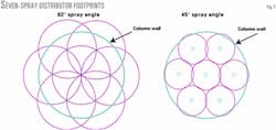
Fig. 5 shows spray footprints at a design angle of 82° and a collapse angle of 45°, both of which spread the quench water evenly. At 82°, the column cross-sectional area has multiple coverages. Sprays extending beyond the column walls bounce off the walls and irrigate the peripheral area, which shows less coverage without the sprays bouncing back.
An extensive experimental program by FRI showed that a multiple coverage spray pattern, similar to that used here, had one of the best performances of all the spray distribution studies.
Column cross section is still uniformly covered with a single layer of spray at 45°; we can expect a reasonable heat and mass-transfer efficiency.
The spray pattern must be fully symmetrical. With a spray nozzle pressure drop far larger than header pressure drop, symmetry promotes an even split of quench water even when some flashing occurs. Fig. 5 shows that the pattern is fully symmetrical.
The success of a good spray pattern depends on the spread, which is a function of the distance between the spray nozzles ends and top row of shed decks. In the quench towers, the available distance was too small, so we had to take out one row of shed decks. Better distribution contributes to heat transfer more than an extra row of shed decks.
Filters
With 1-in. throats, nozzle plugging is uncommon but cannot be ruled out. We have experienced plugging in larger spray nozzles. Polymer and corrosion products can agglomerate in dead pockets, dislodge, and plug the nozzles if large enough. The spray header design avoids dead pockets, but it is not perfect. Dead pockets can also exist in the inlet pipes that were not modified.
We added two full-size filters with no bypass in each quench water circuit to prevent spray nozzle plugging.2 We designed the filters to remove particles 1.5 mm or larger, (17 times smaller than the throat diameter). Sauter and Younts successfully used this procedure to eliminate a pipe distributor plugging problem in DuPont Co.'s water quench tower in Orange, Tex.13 Filtration to 1.5-mm particle size was easy and inexpensive.
Gas distribution improvements
We had an incentive to add a simple gas distribution deflector at the tower feed. Feed inlet velocities were not high enough to justify an elaborate gas distributor. Also, shed decks can tolerate at least some degree of gas maldistribution.
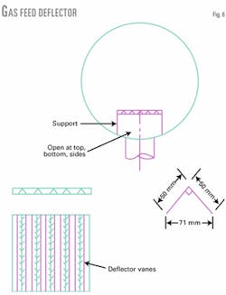
Hydraulic consultant James Litchfield performed the deflector design.14 Fig. 6 shows the deflector. It has simple deflector vanes placed in front of the feed inlet to break up the incoming velocity jet. This is a minor investment that has a major influence on vapor patterns.
New shed decks
The new shed decks have narrow sides (50 mm), with 50-mm gaps. They give excellent liquid curtains, and a good liquid split, both of which improve gas-liquid contact. We retained the 700-mm deck spacing and reused the existing tray support rings and beams for the new decks. Again, these modifications were inexpensive.
Commissioning tests, start-up
One should water test the sprays before starting up the spray system. Lieberman and Lieberman reported that, after installing new packings in a refinery vacuum tower, a water test revealed plugged spray nozzles, spray nozzles missing internals, plugged headers, and leaks.15 The best designs can be ruined by hardware breakage or plugging.
Our water test consisted of filling the first-stage quench tower bottom sump with water and using the normal pumps to circulate this water from tower to tower in the normal circulation route (Fig. 7). We visually inspected the spray action for leaks, broken nozzles, and plugged nozzles.
The test revealed several leaking flanges, which were repaired. Two nozzles produced a nonhomogeneous spray pattern. We replaced them with new nozzles.
During tower start-up, the filters repeatedly plugged with coke and polymer that spalled off from the piping. The filters were cleaned every 2-3 hr after start-up. After a few days the problem went away. Under normal operation the filters are cleaned every 3 months. In the event of a compressor surge the filters require more frequent cleaning.
System performance
Fig. 7 shows data for winter operation after the modifications. Table 1 compares performance before and after the revamp. Temperature approaches between exit gas and quench water entering the quench towers were halved in the first and second quench towers, and declined by over 10° C. in the third.
Additional heat exchanger modifications by Carmel and the added filtration enhanced quench water cooling, especially of the water entering the second-stage quench tower. Overall, the quench tower gas outlet temperatures declined 7-17° C. Hot summer quench tower gas outlet temperatures no longer bottleneck the cracked gas compressor.
Table 1 and Fig. 8 compare volumetric heat-transfer coefficients before and after the modifications. The measured heat-transfer coefficients improved 55-120%.
The best correlation to predict heat transfer in narrow shed decks is Fair's classic baffle tray correlation, which is based on much wider baffles or decks.16 The shed decks we used are much narrower than baffle trays, and have better gas-liquid contact and heat transfer. Fair's correlation, therefore, is conservative for Carmel's shed decks.
Fig. 8 shows that our shed deck design gives heat-transfer coefficients that are 25%, 60% and 100% better than baffle trays as predicted from Fair's correlation. Our shed deck designs should give heat-transfer coefficients about 40-50% better than baffle trays.
Packings with 75 sq m/cu m surface area with excellent vapor and liquid distribution can provide about twice the heat-transfer coefficients of baffle trays.
Packings could have improved the temperature approaches by 1-2° C. in the first and second-stage quench tower, but not in the third. The high heat-transfer coefficient in that tower is what we would expect from 75 sq m/cu m random packing. Heat-transfer benefits from the proposed packings compared to our shed deck designs were minor and economically insignificant.
Epilogue
Higher heat-transfer coefficients are beneficial in short packed beds in which the approach between the gas and quench water temperatures is high. Higher heat-transfer coefficients also help maximize energy recovery from the quench tower, for example, when quench water is used for reboiling a C3 splitter and heat is short. There are many other applications when packings are attractive for quench towers.
In this case, different circumstances dominate. The quench towers contain sufficient height for heat transfer, and we can achieve close approaches with less-efficient shed decks. Good distribution required by packings is difficult to attain and costly due to the letdown of circulating water and the presence of gasoline.
Since the quench towers also serve as gas de-entrainers for the compressors, carryover from an overflowing plugged gravity distributor is unacceptable. The quench towers, therefore, use the lower capital and higher reliability shed decks.
One must use good engineering judgment when evaluating a quench tower. Before settling on a nonoptimum solution, one must collect data and study drawings. It only takes two hours to follow the cookbook method for plotting Fig. 4. No proprietary information is required. It only takes one look at Fig. 4 to conclude that this liquid distributor will not give satisfactory performance.
Understanding the basics allows one to realize that letting down a condensed gasoline-water mixture can generate phase-separation problems in a gravity liquid distributor. This is troubleshooting. Troubleshooting saves money and it also makes the difference between a solution that leads to future operating problems and one that is trouble-free.
References
- Perry, R.H., ed., "Chemical Engineers' Handbook," 7th Ed., McGraw-Hill, New York, 1997.
- Kister, H.Z., "Distillation operation," McGraw-Hill, New York, 1990.
- Senecal, V.E., "Fluid distribution in process equipment," Ind. Eng. Chem., Vol. 49, No. 6, 1957, p. 993.
- Stupin, W.J., and Kister, H.Z., "System limit: The ultimate capacity of fractionators," to be presented at the International Conference on Distillation and Absorption, Baden-Baden, Germany, EFCE, Sept. 30 - Oct. 2, 2002.
- FRI progress report, December 1961.
- Olsson, F.R., "Detect distributor defects before they cripple columns," Chem. Eng. Prog., October 1999, p. 57.
- Strigle, R.F., Jr., "Packed tower design and application," 2nd Ed., Gulf Publishing Co., Houston, 1994.
- Harrison, M.E., "Consider three-phase distillation in packed columns," Chem. Eng. Prog., November 1990, p. 80.
- Mullenix, D., Jordan, M., Bundick, H., Martin, F., and Lewis, V., "Control of carbonyl polymer fouling in caustic towers," proceedings of the 8th Ethylene Producers Conference, 1996, p. 89.
- Cunha, J.A., and de M. Freitas, P.R., "Acid gases absorber improvements in Copene's ethylene plant," AIChE Spring National Meting, Houston, Mar. 9-13, 1997.
- Moore, F., and Rukovena, F., "Liquid and gas distribution in commercial packed towers," Chemical Plant and Processing, European edition, August 1987, p. 11.
- "A spray collapse study," Movie 919, Fractionation Research Inc., Stillwater, Okla.
- Sauter, J.R., and Younts, W.E., III, OGJ, Sept. 1, 1986, p. 45.
- Private communication with Litchfield, J.F., Consultant, Pasadena, Calif.
- Lieberman, N.P., and Lieberman, E.T., "Design, installation pitfalls appear in vac tower retrofit," OGJ, Aug. 26, 1991, p. 57.
- Fair, J.R., "Designing direct-contact coolers/condensers," Chem. Eng., June 12, 1972.
The authors
Henry Z. Kister is director of fractionation technology at Fluor Daniel, Aliso Viejo, Calif. He has more than 25 years' experience in design, troubleshooting, revamping, field consulting, control, and start-up of fractionation processes and equipment. Previously, he worked for Brown & Root, ICI Australia, and Fractionation Research Inc. Kister holds a BE and ME from the University of NSW, Australia. He is a fellow of IChemE and a member of AIChE.
Samuel Schwartz is deputy ethylene plant manager for Carmel Olefins Ltd., Haifa, Israel. He has been involved in process design, economic and energy analyses, optimization and field troubleshooting of fractionators, furnaces, refrigeration and heat exchange systems during his 12 years at the olefins complex. As operation leader of turnarounds and numerous projects, he was in charge of commissioning, startup and performance testing. Schwartz holds a BS in chemical engineering from the Technion - Israel Institute of Technology, Haifa, Israel.
