Isolation methodology ensures safe, flexible facilities
The isolation methodology discussed in this article ensures that an oil production facility can continue to operate or remain pressurized while discrete sections of the facility are taken out of service for maintenance or inspection.
This methodology requires careful analysis not only from the point of view of the process but also from safety and maintenance considerations. Equipment must be isolated with sufficient integrity to provide a safe working environment for personnel and the methodology must include the entire plant including utilities and any package equipment.
The MLN oil and gas production facilities under development in Algeria by Burlington Resources Inc., Talisman Energy Inc., and Sonatrach show how one can apply such a methodology. Entrepose Contracting is the project's general contractor and Paragon-Litwin is the engineering contractor. Both are French companies
The methodology described in this article is based on the principles outlined in guidelines provided in an Oil Industry Advisory Committee (OIAC) document.1 The document applies both to onshore and offshore installations.
MLN development
The MLN field is in a remote desert location north of Block 405a, about 240 km southeast of Hassi Messaoud.
The field will produce a retrograde condensate from the MLN TAG-I reservoir by gas recycling. Oil of varying GORs will be produced from the MLN F1 reservoir and from the satellite fields MLW, MLNW, KMD, and MLC.
The MLN F1 reservoir and the MLN satellite fields will produce initially by natural depletion. After the second year, the operator may select gas or water injection to maintain the reservoir pressures.
The facilities include a central processing facility (with an evaporation pond, flare, crude oil tankage, and export pumps), a permanent accommodation camp, offsites (wellsites, gathering and distribution systems for produced and injected fluids, export pipeline, roads, airstrip, and other civil works).
The MLN facilities can handle about 40,000 b/d of oil production and reinject about 95 MMscfd of gas. They also can treat produced water and dispose of about 15,000 bw/d.
The facilities include:
- Wellsites with a data-transfer system for pressure and temperature monitoring, valve-position monitoring, flow control, and over-pressure protection.
- Flowlines and manifolds that route fluids from 14 producing wells to the production facilities, gas for reinjection from the production facilities to five gas reinjection wells, and injection water from the production facilities to one water injection well.
- Oil-gas-water separation and flash-gas compression.
- Crude oil desalting and dehydration.
- Crude oil stabilization.
- Storage, metering, and export of oil product.
- Oil export pipeline.
- Gas dehydration.
- Enhanced liquid recovery via gas chilling.
- Gas compression for reinjection gas.
- Wash-water (aquifer) pumping into separation train.
- Produced-water treatment for disposal via reinjection, or via evaporative ponds.
- Closed and open drain systems.
- Flare collection and disposal system.
- Utility systems (diesel, fuel gas, chemical injection, instrument and plant air, inert gas, and utility water).
Central processing
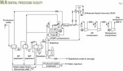
Fig. 1 shows a simplified flow scheme of the central processing facilities (CPF).
The high-pressure (HP) separator receives fluid from the gathering system and normally operates at 40 bara. From there, crude oil with about 5% water flows to the medium-pressure (MP) separator, while gas flows to the glycol unit.
The MP separator operates at 14 bara and besides the crude oil coming from the HP separator can treat any rerun off-spec crude from the off-spec storage. The crude leaving this separator contains about 2% water cut and is pumped to the desalting unit.
The oil reserves in the Berkine region are often coproduced with a supersaturated brine and, therefore, the MLN facility has a two-stage electrostatic desalter unit. Water for desalting comes from a shallow aquifer produced from a nearby Barremian well.
The crude oil leaving the desalters contains about 0.15% bs&w and less than 40 ppm salt. A stabilizer column, operating at 8 bara, stabilizes this crude.
The hydrocarbon liquid recovered in the enhanced liquid recovery (ELR) section serves as reflux and augments stabilized crude recovery. The stabilized crude oil, cooled through forced-draft air-coolers, then goes to floating-roof storage tanks.
Electro-centrifugal pumps, operating at 73 bara, pump the crude into a 16-in. export pipeline that connects to the existing 30-in. OH3 pipeline about 40 km to the north.
A low-pressure (LP) reciprocating compressor, with a discharge of about 14 bara, compresses the flash gas leaving the stabilizer column. The compressed gas, cooled in a forced-draft air cooler, then mixes with gas from the MP separator.
The MP compressor, to about 40 bara, compresses both gases. A common electric motor drives both LP and MP compressors. To improve plant availability, the facility has two LP-MP compression trains.
After the MP gas mixes with the HP separator gas, the gas stream enters a dehydration unit for drying by contacting triethylene glycol. The dried gas goes to the ELR section where the hydrocarbon liquid recovered provides liquid for refluxing in the stabilizer column.
The HP compressor and the reinjection compressor then compresses to about 400 bara the lean gas leaving the ELR section.
The water-treatment unit, consisting of a tilted plate separator followed by an induced gas flotation (IGF) unit, treats the produced water from the three-phase separators, water from the stabilizer water pot, and water from the desalting unit.
The treated water goes to storage prior to being filtered and injected, at about 200 bara, into a disposal well.
Purpose of isolation
In general, a facility should have sufficient isolation valves, blinds, spades, or removable spools to ensure the required degree of isolation of each item of equipment or each section of a facility.
For isolating spared equipment, one must be able to maintain normal operations for the remainder of the facility. For isolating equipment without a spare, one must be able to maintain the remainder of the facility pressurized so as to reduce the time required for a shutdown.
Isolation devices have three distinct functions:
- Enable safe removal from service of an entire system (consisting of equipment, associated pipe, and instruments) while other systems continue to function normally.
- Provide physical proof that one has safely isolated a single item or system from all possible sources of inflow before permitting personnel entry or opening equipment to the atmosphere.
- Provide the means to reinstate the equipment or system safely following a successful maintenance or inspection-testing and repair operation.
General isolation provides a way for separating one process system from another or from any utility system. This is the first step towards achieving positive isolation.
For general isolation of equipment items or sections, the MLN facility will have a double block and bleed when piping is ANSI Class 900 lb or greater.
Class 150-lb systems follow the normal industry practice for nontoxic fluids of having a single valve for isolation and a facility to provide isolation. If a valve leaks, one will have to shutdown additional parts of the facility to provide adequate isolation.
Class 600-lb piping and less in clean service can include an emergency shutdown (ESD) valve as a second block valve if the risk assessment points to a requirement for isolation via double block and bleed. The ESD valve must include a means in the field for disabling remote opening of the valve.
Critical control valves generally will have isolation valves that allow maintenance on the valve with the least possible shutdown of production. When determining the requirement for isolation, one should not treat the control or relief valves as equipment because of the infrequent need for removing them while the facility is online and the short time required for removal.
The risk-assessment method outlined in the OIAC guidelines will determine the level of isolation required for control valves. This generally will lead to single isolation.
Single relief valves would require double-valve isolation if one has to remove them under operating conditions. But spared relief valves usually have single-valve isolation because one can swap the on-line and off-line valve via a key interlock arrangement that ensures the system always has secondary over-pressure protection.
One can remove and repair-replace a faulty valve at the next general shutdown or under a permit to work procedure if replacement becomes urgent.
Positive isolation
One can achieve positive isolation by:
- Rotation of a spectacle blind to its closed position.
- Insertion of the spade element of a spade and spacer set.
- Removal of a spool piece and the subsequent blinding of the open process piping.
In general, one uses spectacle blinds or spade and spacers for positive isolation. Normally one installs spectacle blinds on line sizes up to and including 12 in. and spade and spacers on larger line sizes because of weight constraints.
One uses spool removal on:
- Rotating machines, to aid their removal.
- Shell and tube exchangers, to aid bundle withdrawal.
- Relief valve suction lines, to provide a visual indication that the relief valves are isolated from the vessel and to reduce the possibility of restart and operation with the relief valve still isolated from the system it protects.
Before positive isolation can be effected, one requires general isolation of the system together with depressurization and possibly purging. Positive isolation is needed when an isolated system has to be opened-up for maintenance, inspection, or testing.
Parameters
One should base the selection of the isolation on a risk assessment that considers the effects of the fluid release, the rate at which the fluid could be released, and the likelihood that a release will occur.
The selection process includes such parameters as number of people at risk, facility congestion, fluids released, rate of potential fluid release, fluid pressure, line size, isolation frequency, and isolation duration.
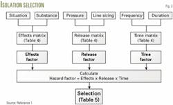
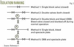
OIAC suggests that one base the selection of an appropriate isolation method on recognizable, readily available parameters. One inputs these parameters to matrices and uses the derived results to determine a hazard factor used to select the isolation method (Fig. 2).
This method is not applicable to pipelines and readers should consult the original reference for this case.
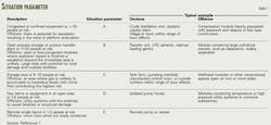
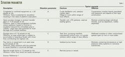
Table 1 provides a "situation parameter" for different installations.
This parameter is related to determining the potential for casualties and escalation or damage in case of a substance release.
One determines the "substance parameter" by the hazardous characteristics of the fluid in terms of its flammability, toxicity, or harmful properties such as corrosivity (Table 2).
Operators typically perform much of the scheduled maintenance during an annual shutdown of the entire facility, but unscheduled maintenance generally will have the frequency shown in Table 3.
Unscheduled isolation of operating equipment typically will be for less than 7 days.
In some cases, however, longer shutdowns might require the entire system to be isolated, depressurized, and safeguarded while the repair is carried out.
Failure of a gas compressor, for example, could result in temporary flaring or loss of production. One should include these possibilities in facility availability estimates.
Hazard factor
The hazard factors determine the type of isolation needed. One calculates the hazard factors from different matrices based on system pressure as well as on the different parameters outlined previously.
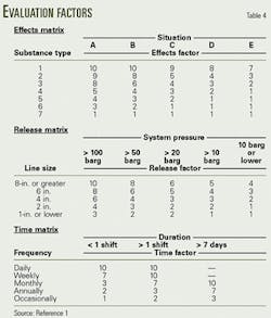
Two parameters, situation (Table 1) and substance or types of fluid (Table 2), indicate the effect that might arise if isolation fails.
For example, vapor cloud explosion (VCE), toxic gas cloud, and jet fire with potential escalation, etc. They provide an "Effects" factor from the effect matrix (Table 4).
In this table, the severity of the situation type must be increased in the case of vapor cloud explosions (VCE) in congested or confined zones, boiling liquid expanding vapor explosion (BLEVE), or jet fires that may have the potential for "knock-on" effects.
Furthermore, in the case of a product containing more than one substance, the most onerous substance type number should be used.
The line size and system pressure usually will determine the potential release rate and, therefore, give a measure of the size of the effect.
These provide a "Release" factor from the release matrix (Table 4).
The hazard generally will vary with the rate of material released, which depends on the square root of the system pressure and the square of the diameter of the rupture hole in the line.
A typical dispersion calculation shows that the area affected is roughly proportional to the square root of the release rate.1
For higher-pressure release systems, one may need more stringent isolation methods.
A frequent isolation for relatively long periods needs (other things being equal) to be of a relatively higher standard than an infrequent one that is in place for only a short time.
These two parameters provide a "Time" factor from the time matrix (Table 4).
More frequent isolations introduce a greater risk that augments as the intended duration increases because it becomes in practice more difficult to maintain procedural controls due to the necessity for handovers between different groups of workers.
In determining the frequency of isolation, one needs to account for the "group effect" of a number of items of similar duty.
For example, a pump with a particular duty might typically require a seal change once every 12 months, and therefore the frequency of isolation in the time matrix would be regarded as being annual.
If the facility, however, had four such pumps that were grouped so that all were served by the same isolation, a monthly isolation frequency would be needed because isolation would be expected four times each year, once for each pump. Monthly is the next frequency step up from annually.
Similarly the frequency of isolation must take account of the multiple effects where a number of isolations are needed to isolate an item.
For example, to isolate a line section might require a single isolation. If this happened every 3 years, the frequency would be regarded as occasional. If the line section required three isolations to isolate it, however, one would need an annual frequency.
The hazard factor for an isolation is derived by combining the contributions of the three factors:
Hazard factor = Effects X Release X Time
The resulting risk factor is a range between 1 (trivial consequence) and 1,000 (disastrous consequence).
OIAC assessed five commonly used isolation methods by using quantified risk assessment techniques (QRA) for the probability of loss of containment (Fig. 3 and Table 5).
MLN facilities
OIAC guidelines were used in the entire MLN oil and gas production facilities. This exercise assured that the safety aspects were integrated in the process design and also facilitated operations and maintenance.
The guidelines do not cover electrical isolation. This is an important associated topic whose principles have been separately established.
The hazard and operability (HAZOP) reviews analyzed the isolation philosophy for each item of equipment and its surroundings, as well as examining critically the final overall facility isolation.
A well-thought-out isolation philosophy does not guarantee completely the safety of the facility.
It was considered very important to involve operations personnel in the development of the isolation principles, in their application to the MLN facility, and in all the HAZOP reviews.
It is vital that operations fully understand the isolation intent and that they are aware of the nature of materials that will be trapped in the equipment, or released from the equipment, while it is being maintained (sour-toxic fluids, oxygen free fluids, etc.).
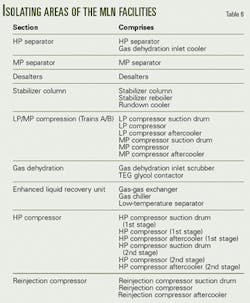
One can isolate spared process pumps individually and other equipment in sections. Table 6 lists the isolation areas for the MLN facility.
Each section is unspared, with the exception of the LP-MP compression train, therefore, one will need to shut-in production to permit maintenance. In these circumstances, one may need to depressurize adjoining equipment to avoid the requirement for double valving.
For the MLN project, the situation parameters (Table 1) are defined as:
- Type B for process area including separation, crude oil stabilization and gas compression.
- Type C for offsite areas including crude oil export storage and pumping.
- Type E for equipment at the wellheads.
The substance parameters (Table 2) are:
- Type 2 for wellhead fluids (40 wt % vaporized on release).
- Type 3 for high-pressure liquids (10 wt % vaporized on release).
- Type 3 for off-spec and stabilized crude oil.
The analysis used the OIAC technique for determining the hazard factors for each individual branch joining each piece of equipment.
The analysis was developed in an Excel calculation spreadsheet incorporating calculations of different parameters needed for determining the hazard factor.
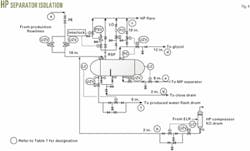
Table 7 illustrated the calculations for the high-pressure separator and Fig. 4 shows the resulting isolation.
Click here to view Table 7: MLN Oil Development Facilties Equipment Isolation PDF.
The isolation adopted in the MLN project often is more severe than that determined using the OIAC technique.
Other safety considerations
Apart from isolations based on the OIAC criteria, the MLN project design also included other major safety considerations.
For instance, confined space entry isolation is a special case not covered by the OIAC recommendations.
Prior to man entry, one must positively isolate all sources of hydrocarbon or hazardous fluids from the vessel. To this end, the vessels fitted with man ways, hand holes, or inspection hatches include spectacle blinds or spade and spacer arrangements on every process and utility nozzle.
The exception is connections to the relief systems, which should be fitted with a removable spool.
Vessels connected to the HP flare system have a globe valve, installed downstream of a tight-shut-off ball valve that enables controlled manual depressurization of the vessel.
Vessels connected to the closed drain system have a similar arrangement, but in this case the upstream ball valve is locked closed.
This ensures, through the permit to work procedures, that materials are discharged to the closed drains system in a controlled way and after vessel depressurization to flare.
This is particularly important in the case of higher pressure vessels containing fluids that might over-chill the drains system when flashed across the globe valve.
Vessels connected to the LP flare system require only a single isolation valve in the manual vent line to the flare.
All pump suction and discharge nozzles have removable spool pieces for maintenance purposes.
Where possible, spool pieces include a 90° bend to facilitate removal. This requirement, however, is based purely on maintenance rather than safety grounds.
Pump casings have vent and drain connections.
Control valves have a by-pass only where the operator can safely control the process, using local indicators, and where the application is justified. Control valves generally do not have hand wheels.
All critical control valves have spares in storage so as to allow quick replacement of the valves.
Removable spool pieces are fitted on the piping associated with the tube side connections of thermal exchangers. This requirement is based on maintenance rather than safety needs.
All compressor suction and discharge nozzles have removable spool pieces for maintenance needs.
Generally one cuts to fit the spool piece on site and fits it exactly to the nozzle after aligning the compressor. This minimizes the operating piping stress on the nozzle.
Compressor casings have vent and drain connections.
For compressors in hydrocarbon service, the drains are hard-piped to the process drain systems.
Compressors may stay at settle-out conditions for extended periods and liquid may accumulate in the compressor casings.
The compressors, therefore, needs connections to the closed drain.
Removable spool pieces, and not spectacle blinds and spacers, provide positive isolation on the vapor lines from the flare knockout (KO) drums and inlet and vapor balance lines on the closed drains drum.
This requirement is for safety and reduces the probability of this equipment remaining isolated after a shutdown for maintenance, inspection, or testing.
ESD valves have upstream isolation where the ESD valve is upstream of the process, and downstream isolation where the ESD valve is downstream of the process.
An ESD valve may form part of the section isolation in Classes 600 lb and less piping. Removal or maintenance of these valves may require a full plant shutdown to achieve the necessary isolation.
Relief valves are spared on unspared continuously operating equipment.
Scheduled replacement and recalibration of relief valves usually takes place during a shutdown.
The relief isolation valves need interlocks. For larger relief valves, one often carries out in situ calibration. This is possible with single isolation using the bleeds as connections to the test equipment.
Full capacity relief valves have spares while valves installed for thermal expansion relief (including the fire case) generally do not have spares.
One may isolate and change out a single thermal expansion relief valve from stored spares under a permit to work system if circumstances allow this.
The risk of a fire under such circumstance is considered to be acceptably low and, provided the system remains on-line, fluid cannot be locked in and thermal expansion from other causes is not a risk.
One regularly opens pig launchers and receivers while they are connected to a live process system.
The safety of their operation depends upon correct implementation of isolation procedures. Interlocks ensure a safe operation.
The pig launchers and receivers also have a mechanical lock safety device to prevent opening the end door while they are under pressure.
The pig launchers and receivers, therefore, will have isolations, venting, and draining facilities.
The OIAC document provides guidelines for the isolation philosophy of pig launchers and receivers.
The isolation guidelines also apply to instruments in the MLN facility. For example, a LSH (level switch high) on the suction scrubber to the last compression stage is a Situation A, Substance 4, Effect 5, Release 4, Duration 3, and Hazard Factor 60.
This requires double valve isolation, provided by valves on the vessel bridle and valves on the individual lines to the level switch.
The equipment isolation philosophy should be complemented witha protection philosophy for rotating equipment in order to acheive a good overall level of plant safety.
The protection of rotating equipment is generally based on the requirements of API 14C.
Acknowledgments
The Controller of HMSO (Her Majesty's Stationery Office), UK, and Queen's Printer for Scotland Crown permitted use of copyright material in Reference 1.
The authors acknowledge the management of Burlington Resources Inc., Talisman Energy Inc., and Sonatrach for their permission to publish this article. The authors also acknowledge Andrew Clarke of Talisman Energy for his helpful comments and input for this article.
Reference
- The Safe Isolation of Plant and Equipment, ISBN 0 7176 0871 9, produced by the Health & Safety Executive, UK.
The authors
Shashi Dharmadhikari is responsible for upstream and gas processing technology for Paragon Litwin, France. He has more than 30 years' experience managing the effective design and operation of process plants. Dharmadhikari holds a PhD in chemical engineering from the University of Surrey, England, and the BS from Bombay University, India. He is a Fellow member of the Institution of Chemical Engineers, UK, and a member of the American Institute of Chemical Engineers.
Tony Bretherton is facilities engineer for Burlington Resources Inc., London. He previously was with Air Products and Badger in the UK. Since 1978 he has worked as an engineering consultant in the UK oil and gas industry, both onshore and offshore, and more recently in oil and gas development in North Africa. Bretherton has a PhD in chemical engineering from Bradford University in England. He is a Member of the Institute of Chemical Engineers and a chartered engineer in the UK.
