Electronic device useful for accurate measurements
An electronic device helped Shell Deer Park Refining Co., Deer Park, Tex., achieve trouble-free measuring of two difficult pipe spools during a distillation unit turnaround.
The tool, called the total station device (TSD), allows three-dimensional measurements with an accuracy of
The device replaces the surveyor's theodolite, which only measures horizontal and vertical angles. In addition to angles, the TSD measures distances.
Beyond the usual land surveys, the TSD can take measurements for the fabrication of new piping spools and handle an array of other measurement challenges.
Measurement problem
In early 1999, Shell Deer Park Refining needed to install two new 24-in. pipe spools, each about 100 ft long, with flanged ends, at an elevation of about 50 ft. The only access for personnel was at the mating flanges of the new equipment at each end.
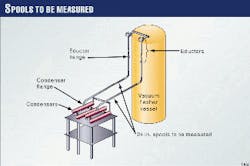
As shown in Fig. 1, each spool began at the outlet flange of a new eductor, suspended from the top of a vacuum flasher vessel, about 85 ft above grade. The new 24-in. spools continued about 35 ft downward, then turned through a 90° ell into a 70 ft long horizontal run. The spool then turned downward through a 90° ell into a 4.5 ft vertical run to connect to the flange on the new first stage condenser.
Although both spools had similar dimensions and ran alongside one another, the two 70 ft horizontal runs diverged at a small angle.
The piping material specification called for post-weld heat treatment as well as hydrostatic tests for the 0.563-in. WT pipe. The specification did not permit slip-on flanges.
Neither spool had sufficient support to allow hydrostatic testing in place. In addition, neither spool was "square with the world." Bolt holes of the new eductor flanges and the new condenser flanges straddled the plant grid; however, the horizontal run of each spool ran at a small angle to the plant grid. It was therefore necessary to rotate the flanges on each end of each spool so the flange bolt holes would align with the equipment flange bolt holes
The bolts for 24-in. ANSI 150 class flanges are 1.25 in. diameter; the flange bolt holes are 1.375 in. diameter. Thus, it was necessary to have an accuracy of at least
This was optimistic, however. ASME B16.5, Pipe Flanges and Flanged Fittings, allows the flange manufacturer tolerances of 1/16 in. on the bolt circle diameter and 1/32 in. on the center-to-center of adjacent holes.
The piping designer could not accurately compute the dimensions of the spools before either the eductor or the condenser was installed. To do so would have required that both pieces of equipment and their supporting structural steel be fabricated and installed to near zero dimensional tolerances.
The original construction plan for each spool called for lifting the three pieces into position, marking them for welding, and returning them to grade for fabrication. For each spool, three field welds were required: one in the horizontal run (to accommodate the required length) and one at each flange for flange rotation and accommodation of the vertical lengths.
This original plan was expensive because cranes were required to lift each spool two times: once to mark for welding and another for installation.
Proposed solution
Parsons Energy & Chemical Group, Houston, provided engineering support during the turnaround. Parsons recommended that, following installation of the new eductors and condensers, the plant use a TSD to measure the location, angularity, and rotation of the four equipment flanges.
Parsons chose Hicad America, Houston, to do the work because its proprietary DIMES software directly and quickly produces dimensioned piping isometrics from the measurement data.
Use of the TSD allowed the spools to be measured, tack welded, and checked at grade. Once the tack-welded spools conformed to the required dimensions, welding, subsequent testing, and post-weld heat treatment proceeded. Valuable crane time was conserved because no lifting of the spools to mark for welding was required.
Total station device
Physical handling for the TSD on a tripod is similar to that of the theodolite on a tripod. Even with an attached computer, the TSD is carried, maneuvered, and taken down in a like manner.
While the theodolite cannot measure distance, the TSD uses electromagnetic distance measurement technology to measure distance from the TSD instrument to a reflector, called a prism.
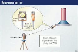
The prism (Fig. 2) is about the size of a golf ball. A Y-shaped metal holder permits its rotation. A spirit level, incorporated into the prism holder, aids accurate positioning of the prism. The holder has a threaded connection that permits rods of various lengths to be connected.
The TSD computer records three-dimensional measurement data. In practice, the data from one shot are only significant relative to the data from other shots. In the simplest case, data may be recorded for the prism at Location A and again when the prism is moved to Location B. The computer output will then report the horizontal distance, the vertical distance, and the straight-line separation between A and B.
In a more complex case, the TSD shoots two points in the plant grid with known X, Y, and Z coordinates and stores the coordinates in its computer. The computer then records the plant coordinates of the prism for each subsequent shot. For piping measurements, knowing the exact location of the prism is useful only to the extent that the information can be translated to the pipe centerline.
In a congested plant environment, it can be difficult to find a position for the TSD that provides a clear line of sight to all points to be measured. Ingenuity, planning, teamwork, and careful communications can overcome these difficulties.
In large measurement jobs, it is commonly necessary to move the TSD several times to collect all of the required data. In some cases, mounting the prism on a long rod of known length can solve problems with obstructions. The technician must adjust the data in the computer to account for the rod length.
In Shell's case, the TSD had an unobstructed line of sight to all the points to be measured. The prism was mounted on a stem of 4 in. in length.
For each shot, the technician aligned the stem of the prism with the line of sight of the TSD (Fig. 2). He was aided for each shot by hand signals from the technician operating the TSD. The computer was programmed to record coordinates 4 in. behind the prism and directly on the line of sight of the TSD.
In a simpler case, the prism could be positioned vertically 4 in. above the point to be measured for every shot. Then every shot would have the same 4-in. error, and the errors would cancel out.
In the past, technicians manually transferred data from the TSD to hand-drawn piping drawings or more recently, to computer-drawn drawings. If the top of flange had been shot with the TSD, coordinates were adjusted by manual calculations to reflect the centerline of the pipe.
Hicad's DIMES software directly receives the TSD data and produces a piping isometric. Although some manual intervention is necessary, the software reduces the opportunity for error.
Execution of the plan
As soon as the new eductors and condensers were installed, the technicians took TSD measurements. Scaffolding permitted the technician with the prism to access the eductor flanges.
Hicad America positioned the TDS tripod directly on one of the condensers, which provided a stable platform with line of sight to all four equipment flanges.
For each flange, it measured coordinates for several bolt holes and several locations on the raised face of each flange. Data were needed to calculate required flange rotation as well as to calculate the location of the vertical centerline of each flange.
Several hours after the measurements were completed, the DIMES software produced two-dimensioned piping isometrics. Along with the expected dimensions, the isometrics showed that the eductor flanges were not horizontal. Instead of looking straight down, they looked down and slightly away from each other.
These data could have been used to cant the flanges on the two 24-in. spools for proper flange make-up. Investigation showed, however, that the eductors were not properly installed. They were in a bind against their supports on the side of the vacuum flasher, with the top piping connections too close together.
Construction personnel repositioned the eductors to proper vertical centerlines. Hicad America then retook the required TSD measurements and produced two new dimensioned piping isometrics several hours later.
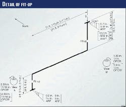
The welding crew tack-welded both spools, and Hicad America and Parsons checked the tack-welded spools. Fig. 3 is the report prepared by engineers to check one of the spools. The specified dimensions are shown in square brackets, the dimensions measured are shown without brackets, and the errors are shown in curved brackets. Thus, the western vertical dimension as tack-welded was 1/4 in. shorter than specified but within allowable tolerances.
The triangles filled with vertical lines indicate the extent to which the welder failed to make the raised face of the flange perpendicular to the centerline of the pipe.
The notations for the upper flange in Fig. 3 have the following meaning: If the centerline of the pipe were truly vertical when the flange was mated with a perfectly horizontal flange looking down, then the raised faces of the two flanges would touch first on the north side, and the separation of the raised faces on the south side would be 3/32 in. across raised face (ARF).
The flange rotation notation for the upper flange shows that, looking into the pipe, the welder is to rotate the flange clockwise 1.9° from the bolt holes' straddle-major-centerlines position. This rotation is equal to an arc length of 1/2 in. on the bolt circle. OPCR stands for over pitch circle radius.
The tack-welded spools were judged acceptable, and final welding began immediately. Following post weld heat treatment, radiographic examination, and hydrostatic testing, the spools were lifted into position and bolted to the equipment flanges. No dimensional problems were encountered.
Other applications
The described pipe-dimensioning problem is only one way that the TSD can be useful. Once the capabilities of the instrument are understood, only the ingenuity and resourcefulness of the user limits its applications.
Parsons has used the TSD to design the replacement of roughly 1,500 ft of 20-in. and 26-in. piping (numerous spools) in a catalytic reforming unit. Measurements of furnace and reactor flange location were taken with the unit in operation at about 1,000° F.
The locations were adjusted for thermal expansion and used for the design of the numerous piping spools required. No dimensional problems were encountered during installation of this piping.
Hicad America has used the TSD for plant relocations. It uses the device to match equipment foundation anchor bolts at the new location with those at the existing location.
Vessel fabrication shops have also used the TSD to verify nozzle locations and overall dimensions. This is especially useful for nozzles set at odd angles.
Parsons has also used the TSD to buttweld a new furnace to adjacent equipment. The connection point was about 5 ft in diameter and several feet long. As the perimeter of the connection point was not a perfect circle, Parsons used the TSD to measure a number of locations around the periphery of each 5 ft diameter weld end.
Parsons used these data to calculate where the centerlines would be if the sections were round. Positioning the new vessel such that the two centerlines intersected at the plane of the buttweld allowed successful fit-up for the buttweld with little difficulty.
The Author
David A. Phelps is a senior project engineer for Parsons Energy & Chemical Group, Houston. In his current assignment, he is responsible for defining the scope of maintenance work in forthcoming turnarounds for a client refinery.
For most of his 9 years at Parsons, he has managed multiple projects in the $25 million and smaller range. Previously, in his career, he also managed projects for Valero Transmission Co. and Phillips Petroleum Co.
Phelps holds a BS in mechanical engineering from Washington State University, Pullman, Wash.


