Method yields download force to arrest upheaval buckling in offshore lines
A simple method for preliminary design of offshore pipelines against upheaval buckling has been developed. It uses an averaging approach for prediction of the required download in the absence of information on the imperfection length.
The method is based on basic beam-column theory; design examples are used here to demonstrate the method.
Upheaval buckling
When a pipeline is operated at a temperature and pressure higher than that at tie-in and greater than the ambient, the pipe will try to expand. If the line is not free to expand, an axial compressive force develops in the pipe that may cause considerable vertical, lateral, or combined movement of the pipe.
When the line is buried in a trench or berm, the lateral soil restraint usually exceeds the vertical uplift restraint created by the pipe`s air or submerged weight, its bending stiffness, and the soil overburden. In that case, the pipe will tend to move upward, and unacceptably large vertical displacements may occur partly to release the compressive force.
The pipe may protrude through the soil cover with or without excessive yielding of the pipe material. This phenomenon in offshore pipelines is called upheaval or thermal buckling.
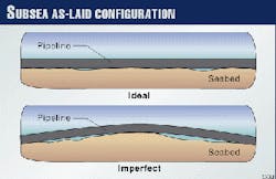
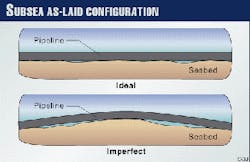
The primary factors affecting the buckling behavior of offshore pipelines include this axial compressive force and the imperfect profile, typically as shown in Fig. 1, initially taken up by the pipeline upon laying.
A literature survey shows that sophisticated analytical and numerical models account for the primary factors plus other relevant design parameters. These include material nonlinearity, large pipe displacement effect, soil cover nonlinearity, and irregular pipe and cover profiles in the upheaval buckling response of offshore pipelines.
An example of this development is a dedicated two-dimensional, finite-element program called UBUCK.1
Previously, Palmer has used the basic beam-column theory to develop a semi-empirical design formula for predicting the required downward load for stability of the pipeline in the operating condition.2
The present analysis differs from that analysis in that in this one, the initial imperfection profile of the pipeline is treated as the source of the upheaval buckling. In the previous analysis, the imperfection profile is taken as the final equilibrium configuration of the pipeline under an axial compressive force.
Beam-column theory
Consider an arbitrary pipeline profile defined by a height (upward deflection) y and a horizontal distance x. The pipeline is idealized as an elastic beam with flexural rigidity E I.
From the basic beam-column theory, the equation of equilibrium for the pipeline under an axial compressive force P and downward force w(x) per unit length can be written as shown in Equation 1 (see accompanying equations box).
The source of upheaval buckling is an overbend "hill" type imperfection in the pipeline profile. For upheaval buckling, consider a symmetric imperfection profile yi with d = height and L = length defined by Equation 3.Assuming that w(x) represents the downward force required to maintain the pipeline in equilibrium in this initial imperfect position, Palmer has solved for w(x) by substituting Equation 3 into Equation 1. The resulting w(x) is a sinusoidal function of x and has its largest numerical value at the crest of the imperfection (i.e., x = 0).
The largest numerical value wc per unit length is a linear function of two terms L-2 and L-4, as defined in Equation 4.
Palmer has rewritten Equation 4 in terms of dimensionless parameters fw and fL (Equations 5-7).Palmer has considered that Equation 5 applies to a particular profile shape, but the specific shape only affects the coefficients and not the general form of the equation. Based on this consideration and the results of numerical calculations with the UBUCK program, Palmer has developed the semi-empirical relations, as shown in Equations 8-10.
Palmer has noted that, in most preliminary design contexts, the designer can determine the maximum height (d) but not the length (L). An imperfection length has been estimated from an assumption that the pipeline takes up an imperfection profile dictated by the interaction of its flexural stiffness with its weight in the installed condition.Substituting this estimated length into Equation 10 and replacing the largest numerical value wc in fw with a uniformly distributed load wo, Palmer has arrived at the design (Equation 11) formula for the required downward load for stability in the operating condition.It should be noted that the coefficient of 1.16 in Equation 11 may be replaced with 1.13 to correlate better with the coefficients 9.6 and 343 in Equation 10. More importantly, arbitrarily replacing wc with wo in Equation 10 to develop Equation 11 is questionable.
Palmer does not provide the analytical procedure required for estimating the imperfection length from the assumption. The imperfection length estimated, however, can be back calculated from Equations 10 and 11 to yield Equation 12.
Since Equation 11 is valid for fL > 8.06, substitution of Equation 12 in Equation 7 yields the condition (Equation 13) that must be satisfied to use Equation 11.It can be shown that under this condition, the uniform load wo from Equation 11 will always have positive numerical values indicating download. When this condition is violated, the formula (Equation 14) may be used for wo, which can be obtained by substituting Equation 12 in Equation 9.
Imperfection profile
The initial imperfection profile of a pipeline is an equilibrium configuration generated by the pipeline`s installation weight as it acts to deflect the pipe in conforming to the pipeline`s trench bottom.
An axial compressive force P subsequently applied to the pipeline will interact with the imperfection profile to alter the pipeline configuration from the initial one.
Assume that this altering pipe movement is resisted by a uniform downward force wa superimposed on the pipe installation weight. Then, Equation 1 may be rewritten as Equation 15.
It is appropriate to assume that ya satisfies the boundary conditions shown in Equation 16.
First, introducing Equation 3 in Equation 15 and solving for ya for the boundary conditions will yield the relationship (Equation 17). It can be shown (Equation 19a) that ya vanishes at the crest of the imperfection when wa = w1.
Using L`Hospital`s rule for l equal to the even numbers (2, 4, 6, etc.), Equation 19a can be expressed as in Equations 19b and 19c. (L`Hospital`s rule is a universally accepted rule for finding a limit value of a dependent variable defined by denominator and numerator as they both tend to zero or infinity for a given independent variable.)Second, consider a symmetric imperfection profile yi with d = height and L = length defined by Equation 20.This imperfection profile represents a shape similar to the deformed shape considered in UBUCK, defined by Equation 21.
It is interesting to show that taking the fourth-order derivative of Equation 21 with respect to x and equating the result with (gii / E I) can yield a relationship similar to Equation 12, as shown in Equation 22.Introducing Equation 20 in Equation 15 and solving for ya for the boundary conditions given by Equation 16, the relation (Equation 23) can be obtained.
It can be shown (Equation 24) from Equation 23 that ya vanishes at the crest of the imperfection when wa = w2.
With L`Hospital`s rule for l equals to 1 and 3 and even numbers, Equation 24a can be expressed as Equations 24b, 24c, and 24d.For visual comparison, the downward forces according to Equations 19 and 24, respectively, are tabulated (Table 1) for several discrete values of l.
This table shows that the two imperfection profiles considered will yield virtually the same downward forces which make the uplift deflection (ya) vanish at the crest of the imperfection.
It can be shown that the same holds true for other values of l > 0. The table also shows that a smaller value of l produces a larger downward force.Preliminary design
The design consists of determining the uniformly distributed downward force large enough to restrain the pipe upward deflection within a tolerable limit.
For a subsea pipeline in trench, the required downward load for stability consists of the submerged weight of the pipeline in operation plus the cover resistance that can be mobilized. As an approximation, the required download may be assumed to be equal to the downward force w1 per Equation 19 (or w2 per Equation 24) plus the pipe`s installed weight.
It was impossible here to derive the imperfection length similar to Equation 12. To be able to use Equation 19 for the design purpose, however, the following approach is proposed:
- Step 1: Calculate the allowable axial stress in compression from the von Mises` yield criterion defined by Equation 25.
- Step 2: Determine the imperfection length Ly from the relation in Equation 26.
The left side of Equation 26 represents the maximum bending stress at the crest of the imperfection with K equal to 2 and 3 for the first and the second imperfection profiles, respectively.
Since Ly is proportional to K1/2, Ly for the second profile is always equal to (3/2)1/2 (= 1.2247) times of Ly for the first profile, with their mean value Lm (Equation 27).
Equation 27 may be rewritten in a nondimensional form as shown in Equation 28.
Step 3: Calculate the downward force (for example, wm1) corresponding to Lm and add this force to the pipe`s installed weight to obtain the required download for stability.Alternatively, calculate two different downward forces for each value of Ly and their mean value (for example, wm2) may be added to the pipe`s installed weight for the same purpose.
In numerical magnitude, insignificant difference would be found between the numerical values of wm1 and wm2, while the former involves less calculation than the latter. Therefore, calculation of wm1 is recommended for determination of the required download.
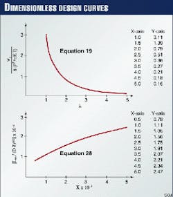
To facilitate application of the proposed approach, Equations 19 and 28 are presented in Fig. 2.
Examples
Two examples illustrate the method.
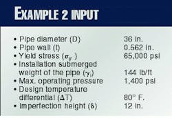
The first is the same example from Palmer: a 10-in. subsea oil pipeline in trench. (See example box for input to Example 1.) The second example is a hypothetical, large-diameter (36 in.) subsea oil pipeline in trench.
Example 1. H represents the cover depth from the top of the pipe to the seabed surface. It should be noted that the pipeline tie-in temperature is not provided by Palmer, and therefore, the axial compressive force P cannot be calculated directly from Equation 2.The actual downward load that can be mobilized is equal to the sum of the pipeline`s submerged unit weight (go) and the uplift resistance of the cover (q). For cover depths of 0.7 m and 0.8 m, the corresponding actual vertical loads can be calculated to be 321.6 lb/ft and 381.2 lb/ft, respectively.Palmer has indicated that for an H of 0.7 m, the ratio between the required value calculated from Equation 11 and the actual value of 321.6 lb/ft is 1.11, and for an H equal to 0.8 m, the ratio is 1.32.
From this indication, the downward force wo can be determined to be: wo = 321.6 / 1.11 ( 381.2 / 1.32 ( 289 lb/ft.
Substituting this value in Equation 11, the axial compressive force P can be back calculated as approximately 0.4126 x 10⁶ lb.
Palmer has also indicated that a series of Level 1 (elastic) UBUCK calculations is carried out for the example problem but provides no information regarding the imperfection profile type and length used for the calculations.
The calculation result described includes that if H = 0.7 m, the pipeline begins to uplift at the top of the imperfection at a temperature of about 70° C., some 10° C. short of the operating temperature. If the cover is 0.8 m, movements begin at about 80° C. Comparison of the downward force of 289 lb/ft with the UBUCK calculation result indicates that Equation 11 underestimates the required download by a factor of 1.32.
For P = 0.4126 x 10⁶ and sh = 26,752 psi, E a DT can be back calculated to 23,788 psi. With these values, the design value of w1 can be calculated as follows:Step 1: sa = 41,970 psiLy = 122.2 ft over Lm = 111 ft (Second profile)
(Equation 27)
Alternatively, w1 = 416.1 lb/ft (L = 99.8 ft)
w1 = 288 Lb/ft over Mean = 352 lb/ft times(L = 122.2 ft
Finally, the required downward load for stability can be calculated to be 342.4 + 40.5 = 382.9 lb/ft. This value agrees very well with the UBUCK calculation result that if the cover is 0.8 m, movements begin at about 80° C. The actual load that was calculated for this cover depth is, as indicated previously, equal to 381.2 lb/ft.
Therefore, in place of Equation 11, Equation 14 should be used to calculate the required downward load. Equation 11 yields a negative value of -212.6 lb/ft for wo, indicating that the calculated force is an upward load, while Equation 14 yields a download of 96 lb/ft which is smaller than the installed pipe`s unit submerged weight.
The required download based on the present method can be calculated as follows.
Step 1: sa = 29,705 psiThen, the required download for stability can be calculated to be 378.9 + 144 = 522.9 lb/ft. Assuming that all of the uniform force of 378.9 lb/ft has to be mobilized from the same cover material as Example 1, the required cover depth can be calculated to be 1.8 ft (0.55 m).
For this assumed cover material, the minimum code-required cover depth of 2.5 ft (0.76 m) is sufficient for the protection of the pipeline from the upheaval buckling.
In the absence of a refined analysis such as the UBUCK calculation of the problem, it is difficult to decide which design result, 96 lb/ft or 522.9 lb/ft, better approximates the true design.
Subjectively, however, the download of 96 lb/ft is clearly a gross underestimate of the true design load because it is even smaller than the installation submerged unit weight.
References
- Klever, F.J., van Helvoirt, L.C., and Sluyterman, A.C., "A Dedicated Finite-Element Model for Analyzing Upheaval Response of Submarine Pipelines," Proceedings, 22nd Annual Offshore Technology Conference, Houston, 1990.
- Palmer, A.C., Ellinas, C.P., Richards, D.M., and Guijt, J., "Design of Submarine Pipelines Against Upheaval Buckling," Proceedings, 22nd Annual Offshore Technology Conference, Houston, (1990).


