FCC revamp improves operations at Australian refinery
The 1998 revamp of the No. 2 fluid catalytic cracking unit (FCCU) in the Caltex Refineries (NSW) Pty. Ltd. refinery at Kurnell, Australia, corrected problems that constrained the unit's operating flexibility.
The design included a new air distributor, a new spent-catalyst distributor, and new stripper internals. In addition, an inertial separator installed during the riser revamp of 1989 was replaced with riser cyclones.
The revamp resulted in a significant improvement in regenerator and stripper performance as well as improved yields and less catalyst deactivation. This article describes the nature of the problems addressed by the revamp, the features of the new equipment, and the early operation of the modified unit.
Unit background
The No. 2 FCCU, which came on stream in 1961, is a 1960s vintage UOP side-by-side unit. It was originally designed as a bed cracker and operated with partial carbon monoxide (CO) combustion regeneration. The regenerator later switched to complete combustion operation.
As a bed reactor, the riser terminated in the lower section of the reactor vessel, and a catalyst bed accumulated in the reactor.
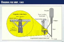
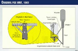
The unit was equipped with a hot wall riser and reactor and a hot wall stripper and spent-catalyst standpipe (Fig. 1). There was a single feed-injection nozzle located at the base of the riser. The stripper was equipped with disc and donut baffles.
The regenerator design included tangential spent-catalyst entry. Regeneration air was injected through a 5 Cr, 1/2 Mo alloy pipe grid. The nozzles in the pipe grid were single diameter inserts located on the numerous branch arms.
There was no refractory lining on the grid. Instead, the top of the grid was protected by a catalyst dam that created a region of dead catalyst on top of the grid.
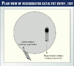
Regenerated catalyst was withdrawn from the regenerator bed above the air grid. The regenerated catalyst standpipe passed through the air distributor. Fig. 2 shows a plan view of the regenerator and the location of the spent-catalyst entry and regenerated catalyst withdrawal.
Air distributor replacement
Mechanical problems with the original air distributor led to its complete replacement with a 304H stainless steel pipe grid in 1982.
The grid design was also modified to address problems with stress-induced cracking and distortion. The new distributor replaced the rigid triangular bracing structure with a more flexible design that used elbows. It also eliminated the hard connection between the central air inlet piping and the four main branch headers.
Instead, all of the air flowed through the branch support piping. The ends of the branches were free to move within limits set by guides on the air inlet pipe and on the regenerator wall.
The use of catalyst dams was retained, and the distributor was not refractory lined. The single-diameter nozzles were also retained in the new design as well as the practice of butt welding the distributor arms to the branch headers. As before, a blanking pattern was used to adjust the air distribution to account for the uneven carbon distribution across the regenerator bed.
It soon became apparent that the new air distributor was no more reliable than the original one. Differential distortion of the distributor arms resulted in air-jet impingement and erosion of adjacent arms.
The four main air headers distorted and became out of round with some movement at the elbows. When reinforcement was added to address these problems, the entire set of arms sagged. This distortion affected the air distribution.
Cracking of the distributor was also a common problem.
Also, uneven carbon distribution caused by the tangential entry of the spent catalyst continued to cause uneven combustion in the regenerator bed. This manifested itself as uneven temperatures in the cyclone outlets, which is not unusual in regenerators of this design.
Riser, regenerator modifications
In 1989, the unit was converted to all riser cracking. As a part of this conversion, the original hot wall riser was replaced with a new cold wall design. This new riser was fitted with multiple atomizing feed nozzles located around the riser circumference. The riser was also extended into the reactor vessel and fitted with an inertial separator device.
The reactor and stripper vessels were also converted to cold wall through the installation of internal insulation. The hot wall spent-catalyst standpipe and slide valve were replaced with cold wall equipment as well.
The revamp also included removal of the disc and donut baffles from the stripper and installation a new stripping steam ring.
One purpose of the revamp was to increase the capability of the unit to process heavier feeds. The refinery has only a small 22-23,000 b/d vacuum tower; thus, most of the feed to the FCC is atmospheric resid.
The revamp increased FCC capacity to 24,000 b/sd and riser temperature limits to 540° C.
At this time, the uneven cyclone temperatures in the regenerator limited unit operation. The hottest cyclone set the limits on feed rate, feed quality, and unit severity. To correct this problem, the spent-catalyst standpipe was fitted with a "ski jump distributor," which redirected the spent catalyst from tangential to radial entry. It was expected to spread the spent catalyst more evenly over the top of the regenerator bed.
Since the "ski jump" changed the catalyst distribution, the air distributor blanking pattern was adjusted as well. The new pattern still directed more air into the section of the bed nearest to the spent-catalyst entry.
Unfortunately, the regenerator revamp did not correct the uneven cyclone temperatures, which continued to limit unit operations. Modified blanking patterns on the regenerator air distributor failed to improve the situation.
Although the product yields from the unit clearly improved, other problems emerged.
The delta coke on catalyst was higher than expected, thus limiting the unit's heavy feed capacity. In addition, the unbaffled stripper required a high stripping steam-catalyst ratio (3-4 kg steam/tonne of catalyst). This, coupled with the atomization steam required by the new feed nozzles, increased the sour water produced from the fractionator overhead system.
Since the regenerator air distributor was not replaced during the 1989 revamp, it continued to be a source of mechanical problems on the unit.
Analyses
In 1991, a Caltex team began analyzing the regenerator problems. Initially, this work focused on both the mechanical problems with the regenerator air grid and the uneven cyclone temperature profile.
Air distributor design
Previous analysis by refinery staff revealed that the design of the air distributor allowed the main branch headers to flex during normal operation. This flexing action, along with differential thermal expansion, was the primary cause of cracking in the air distributor. Cracks occurred at both welds and at high stress locations.
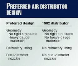
Table 1 compares the desired design features (geometry, refractory lining, nozzle) of an air distributor with the No. 2 FCC air distributor. The existing distributor did not contain most of the desirable features. It was apparent that the existing air distributor needed to be replaced (and not modified) with a new design.
A well-designed air distributor has the following features:
- Geometry.
The geometry of a good distributor must provide for mechanical strength but retain sufficient flexibility to avoid failure due to mechanical stress. For a pipe grid, rigid structures (such as triangular bracing) should be avoided, but individual components should be constructed of heavy gauge materials.
- Refractory lining.
Refractory lining on the outside of the air distributor serves two functions. First, the lining protects the distributor from possible erosion. While average velocities in the regenerator bed are usually low enough to preclude severe erosion problems, turbulent eddies can create localized areas of high velocity and high erosion potential.
Second, and probably more important, the refractory lining equalizes the metal temperature of the air distributor. By its nature, the air distributor exists at the interface between the active combustion zone (above the air distributor) and a cooler noncombustion zone below the distributor.
This difference in temperature produces differential expansion and thus, stress over the height of the distributor. Over time, this stress results in bowing or warping of the distributor, and in severe cases, mechanical failure of distributor components.
Even a relatively thin layer of high-density, erosion-resistant refractory provides some resistance to heat transfer. This, coupled with the flow of cooler air through the distributor, reduces the difference in metal temperature between the top and bottom of the distributor.
- Nozzles.
Nozzle design must provide sufficient pressure drop to distribute the air evenly to all the nozzles and to prevent the backflow of catalyst into the distributor.
To achieve this, the pressure drop through upward-pointing nozzles should be no less than 30% of the static head of catalyst bed above the distributor. For downward-pointed nozzles, the pressure drop should be no less than 10% of the static head.
At the same time, the nozzle exit velocity must be low to prevent nozzle erosion and catalyst attrition. This second requirement is usually in conflict with the velocity needed to meet the minimum pressure drop requirements.
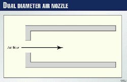
These conflicting requirements generally preclude use of single-diameter nozzles. Thus, modern air distributor designs use dual-diameter nozzles, such as shown in Fig. 3.
In this design, much of the nozzle pressure drop occurs at the nozzle entrance and where the air expands into the larger nozzle tube. The nozzle tube diameter provides low exit velocity to avoid attrition and erosion. The size of the orifice diameter gives the required pressure drop.
Cyclone temperature profile
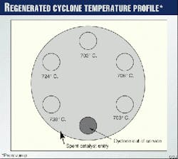
Fig. 4 shows a typical cyclone temperature profile for the No. 2 FCCU. The outlet temperature of the two hottest cyclones was 20-30° C. higher than that from the other cyclones. At times, this temperature difference was as much as 50° C.
Cyclone temperatures were up to 70° C. higher than the regenerator bed. The uneven temperature profile and high dense/dilute temperature difference limited the flexibility of the FCCU in terms of feed quality, operational severity, and feed rate.
The hottest cyclone (No. 2) was located just above the spent-catalyst entry.
High cyclone temperatures usually occur as a result of the combustion of CO that has escaped the bed and come into contact with excess oxygen in the flue gas. When there are localized high cyclone temperatures in complete combustion regenerators, it is usually as a result of localized CO breakthrough. When this CO contacts the excess oxygen in the rest of the flue gas, it ignites to create localized afterburn.
Localized CO breakthrough results from poor air or catalyst distribution. When spent catalyst is spread unevenly over the regenerator bed, areas of high carbon concentration occur where the catalyst enters the regenerator.
The flue gas leaving these high-carbon sections of the bed will always contain some CO and generally be oxygen lean. The flue gas from the remainder of the bed will, however, contain little CO but will contain excess oxygen.
When flue gasses from the two sections mix, CO from the high-carbon section of the bed contacts the excess oxygen and ignites. This almost always occurs above the high carbon section of the bed.
Adjusting the air distribution will usually have a limited effect. Increasing the air in the high carbon zone will increase the rate of carbon burning and thus decrease the amount of unburned coke in this section of the bed.
But it will be impossible to burn all of the carbon in this section. As long as there is a significant amount of carbon on the catalyst, there will always be some CO in the flue gas leaving this section.
The problem can only be corrected by distributing the catalyst evenly across the regenerator cross section. This was the purpose of the "ski jump" distributor installed in 1989.
The "ski jump" directed the catalyst leaving the spent-catalyst standpipe toward the center of the regenerator. In addition, it redirected the catalyst flow so that it was essentially horizontal above the regenerator bed.
Distributors of this type depend on the momentum of the catalyst. Thus, they must discharge above the bed to be effective. Even so, the catalyst flowing down the standpipe may have insufficient momentum to provide full distribution.
In the case of units originally designed with tangential entry, some of the available energy in the catalyst is lost in redirecting the flow in a radial direction decreasing the energy available for distribution.
A second possible cause for the uneven cyclone temperature profile was the presence of volatile hydrocarbons in the spent catalyst leaving the stripper. As previously discussed, the stripper baffles were removed in the 1989 revamp.
Despite the high levels of steam to the stripper, the stripper performance was poor. In hindsight, this was not unexpected since other units equipped with unbaffled strippers also performed poorly.
Any volatile hydrocarbons in the spent catalyst would flow directly to the regenerator dilute phase, where they could ignite and cause high temperatures in the cyclones.
While this was possible, the Caltex team was aware of similar problems on units with momentum-based catalyst distributors and effective strippers. Thus, the team concluded that the primary cause of the uneven temperature profile was poor catalyst distribution and that a new catalyst distributor would be required.
FCC revamp, 1998
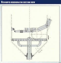
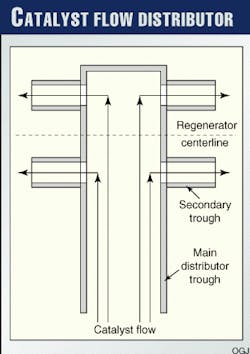
The regenerator revamp consisted of a new spent-catalyst distributor, a new air distributor, and a modified regenerated catalyst standpipe (Fig. 5). The spent-catalyst distributor uses an extension of the spent-catalyst standpipe to direct catalyst into an air-fluidized trough that extends just past the vertical centerline of the regenerator. Fluidization air velocities in this trough are low so that the density of the catalyst is close to the apparent bulk density.
Catalyst leaves this main trough through four smaller troughs (Fig. 6). These spread the catalyst across the regenerator bed. Flow through these troughs is based on the density difference between the highly fluidized catalyst in the regenerator bed and the minimally fluidized catalyst in the trough.
The top of the catalyst distributor is below the regenerator-bed level. This location prevents volatile hydrocarbons entering the regenerator from escaping directly into the dilute phase.
Since the new catalyst distributor spreads the catalyst across the regenerator, uneven air distribution is no longer necessary. Caltex chose a pipe-grid distributor to provide full coverage of the regenerator cross section, to increase mechanical reliability, and to facilitate installation using the existing air-inlet nozzle.
The original regenerator design placed the regenerated catalyst withdrawal in the active bed above the air distributor. In this design, the regenerated catalyst standpipe passed through the level of the air distributor. Where this occurred, no air was injected into the bed.
To eliminate this potential area of poor air distribution, Caltex moved the regenerated catalyst withdrawal to below the air distributor. The new withdrawal point was placed as low as practical in the regenerator vessel (Fig. 5). The short extension into the vessel serves to prevent poorly fluidized catalyst from the regenerator wall from entering the standpipe.
Other unit modifications
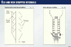
Caltex installed new baffles for the unbaffled stripper during the revamp. Traditional baffle designs for this type of unit (Fig. 7a) consist of disk baffles attached to the riser alternating with donut or ring baffles attached to the stripper shell.
Disk and donut baffles are easy to install during unit construction or in revamps of hot wall strippers. For cold wall stripper revamps, however, the associated refractory work has a negative impact on the revamp schedule.
To avoid this problem, Caltex developed a baffle design that did not require attachments to the stripper shell (Fig. 7b). There are seven levels of baffles. Each level consists of six cantilever baffles attached to the riser. Each successive level is rotated so that the entire stripper cross section is covered in three levels. The spacing between each level allows for reasonable access as well as proper catalyst/steam mixing.
This baffle design allows for preassembly of baffles onto a new riser section prior to the unit shutdown. This preassembly minimizes the amount of installation work required during the actual shutdown.
The baffles themselves have sloped tops to facilitate the downward flow of catalyst over the baffles. At each level, steam is distributed through the use of holes in the baffles as well as notches in the base of the baffles.
The refinery also replaced the existing riser termination device with riser cyclones. The design for this modification was awarded to a major FCC licensor.
Evaluation of the combined effects of the various modifications indicated that the catalyst circulation would exceed the capacity of the existing regenerated catalyst standpipe and slide valve.
This problem was addressed by adding the design of a larger standpipe to the scope of the licensor's work. This also allowed the refinery to replace the last hot wall section of the unit with cold wall construction.
Performance of revamped unit
The revamped unit started up in early 1998. Based on the cyclone temperature profile, the stripper performance, and the new yields, the revamp was a success.
- Cyclone temperature profile.
Following the revamp, the cyclone temperature profile showed major improvements.
Typically, the cyclone outlet temperatures show no more than a 10° C. deviation between the hottest and coldest cyclone. The temperature difference between the dense bed and the hottest cyclone is 10-40° C.
- Stripper performance.
Stripping steam requirements dropped from 3.5 kg/tonne to as low as 1.8 kg/tonne on light feeds. Despite this decrease in stripping steam rate the regenerator bed temperature remained low.
In addition, catalyst activity has been substantially higher since the revamp-70 vs. 61 to 62 microcactivity (MAT). This has allowed the refinery to reduce catalyst make up to reach an activity target of 65 MAT.
The increased catalyst stability indicates improved stripping and thus a lower level of volatile hydrocarbons in the regenerator. Volatile hydrocarbons burn quickly and thus create high particle temperatures that increase catalyst deactivation.
Stripper performance is also much more responsive to changes in the stripping steam rate. This allows for easier tuning of unit performance with changing feed stocks.
- Yield improvements.
The primary incentive for upgrading the riser-termination device was to decrease dilute phase reactor cracking in the unit. Dilute phase cracking is known to be less selective to desirable products than riser cracking.
One of the primary undesirable products from dilute-phase cracking is dry gas.
Prior to the revamp, the dry-gas yield averaged 48 normal cu m/cu m of feed. After the revamp, this decreased to 38 normal cu m/cu m, a decrease of more than 20%.
Post revamp yields of propylene and the gasoline octane were unchanged at approximately one half of the prerevamp ZSM-5 addition rates. This indicates that another benefit from the revamp is a reduction in hydrogen transfer.
Hydrogen transfer reactions reduce the yield of light olefins and also lower the research octane number of the cat gasoline. Hydrogen transfer reactions have a lower reaction rate than cracking reactions. Thus, they are less likely to occur in units with short contact-time reaction systems.
The Authors
Joseph W. Wilson is a consulting engineer at Barnes & Click Inc., Dallas. Before joining Barnes & Click, he served as a senior consultant at KBC Advanced Technologies, Houston, and as the in house technical consultant for FCC at Caltex Petroleum Corp., Dallas. Wilson designed the revamp described in this article during his employment with Caltex.
In 25 years, Wilson has also worked for M.W. Kellogg and Akzo Catalysts. He has served as an NPRA panelist on refinery technology, and he is the author of "Fluid Catalytic Cracking, Technology and Operation," published by PennWell Publishing Co., Tulsa.
Wilson holds a BS in chemical engineering from Oklahoma State University, Stillwater, as well as an MS in chemical engineering and an MBA from the University of Houston.
Chris Ross is a senior process engineer with Alliance Refining Co., Map Ta Phut, Thailand. He began his career with Caltex Refineries (NSW), Kurnell, in 1984 and has worked in process engineering roles on most types of refining processes and on several major revamp projects on FCC units.
Ross is currently on assignment to Alliance Refining Co., working on the RFCCU and helping develop local process engineering knowledge. He holds a BE in chemical engineering from University of NSW, Sydney.
