Venezuelan plant expansion weighs modification, replacement
Simulation of operations at Pdvsa Western Division`s Ulé LPG complex (Zulia) indicated changes to operating pressures to expand fractionation capacities were preferable to replacement of existing towers.
Several optimization projects already in progress will increase the NGL production by 12,200 b/d. As a result, Pdvsa decided to study existing fractionation facilities and utilities systems.
The evaluation revealed that some of the fractionation towers would have some limits processing the expected additional production.
Ulé complex
Three fractionation plants constitute the Ulé LPG complex. Two fractionate NGL into propane, butanes mix, and gasoline; the other separates the butanes mix into iso- and normal butane.
The LPG-1 plant was built in 1958 and can process about 13,500 b/d. In 1971 the LPG-2 plant was built and originally designed to process 41,635 b/d. The LPG-3 was designed and built in 1980 to fractionate 19,000 b/d of the butanes produced in LPG 1 and 2.
Several optimization projects already in progress will increase the NGL production by 12,200 b/d. These projects include a new plant (LPG-5) and NGL-recovery increase through natural gasoline recirculation in Tía Juana-2 (TJ-2) and TJ-3 plants, offshore Lake Maracaibo.
On the other hand, Pdvsa`s gas-processing strategy 1998-2004 includes other new projects, such as LPG-6 fractionation plant with additional butane-mix production.
Study bases
Because of these plans, Pdvsa undertook a study of the existing fractionation facilities and utilities based on plant feeds and product specifications.
The LPG-1 plant will process 16,658 b/d of NGL from the new LPG-5 plant (currently under construction), which is higher than its proven capacity.
The NGL produced in TJ-2 and TJ-3 plants and the additional production from the NGL recovery increase through the natural gasoline recirculation project will be processed by the LPG-2 plant.The LPG-3 plant feed was determined to consist of the butanes mix from LPG-1 and LPG-2 (14,756 b/d) and to include the butane mix produced by the new LPG-6 fractionation plant (21,460 b/d).
Following are the product specifications, from GPSA:
- Propane Vapor pressure @ 100° F. < 223 psia C4 < 2 vol %
- Butane Vapor pressure @ 100° F. < 85 psia C5/n-C4+ < 2 volume %
- Gasoline Vapor pressure @ 100° F. < 13.5 psia
- Iso-butane C3 < 0.32 mole % n-C4 < 3.41 mole %
- Normal-butane i-C4 < 1.56 mole %
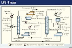
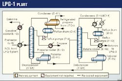
The LPG-1 fractionation plant (Fig. 1) was originally designed to process 17,000 b/d of NGL. Because of its limited heat-exchanger capacity, however, and flooding problems in the fractionation towers, it was found that in fact it can only fractionate some 13,500 b/d.
The plant consists of a depropanizer tower (T-5A, Fig. 1) and a debutanizer tower (T-6A).
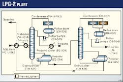
The LPG-2 fractionation plant (Fig. 2) was built in 1971 and designed to have a feed capacity of 41,635 b/d but currently fractionates only 38,000 b/d. It also has two towers, depropanizer (D8-504) and debutanizer (D8-506).
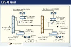
In the LPG-3 fractionation plant (Fig. 3), the butanes mix is separated into iso-butane and normal-butane. The plant was designed in 1980 to process some 19,000 b/d but currently fractionates only 11,000 b/d. It consists of a deisobutanizer tower (D8-0502) and a depropanizer tower (D8-0304).
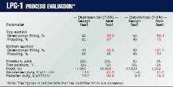
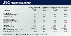
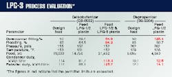
Process simulations of the LPG-1, LPG-2, and LPG-3 plants were made with the new feed flows and compositions, taking into consideration the actual design conditions. Results of those simulations are summarized in Tables 1 (at right), 2, and 3.
The evaluation determined that the depropanizer (T-5A) and the debutanizer (T-6A) in the LPG-1 plant show some problems in their hydraulic performances along with heat-transfer equipment limitations. These problems would prevent their being able to process the new feed under the design conditions.
(Table 2 at right)
The depropanizer (D8-504) of the LPG-2 plant is able to process the new feed of 40,768 b/d, but the debutanizer floods under the new feed conditions.
(Table 3 at right)
For the LPG-3 plant, it was determined that the deisobutanizer (D8-0502) would be able to process the butanes mix from LPG-1 and LPG-2 plants. But the depropanizer (D8-0304) would be unable to handle the liquid load, showing high downcomer-filling percentages and requiring higher heat duties than available.
The D8-0502 tower shows limitations to process the butanes mix coming from LPG-1, LPG-2, and the future LPG-6 plant, as a result of excess in the flooding and downcomer-filling permitted values. In addition, the heat-duty requirements are higher than available.
Alternatives analysis
Simulations were run of alternative solutions for several towers.
Depropanizer (LPG-1 plant)
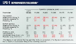
The depropanizer tower (T-5A) was simulated within a range of operating pressure between 285 and 150 psia (Table 4).
The results show that the liquid and vapor loads in the trays decrease when the operating pressure drops, causing tray-performance parameters to fall below the predetermined limits at 175 psia.
Additionally, when the pressure is lowered, the volatility of the propane relative to the butane volatility increases, making the separation easier and also reducing heat-duty requirements.
With the tower operating to 175 psia, the required reflux temperature would not be obtained with cooling-water exchangers, making it necessary to replace them with a refrigerant condenser.
On the other hand, the LPG-5 plant will replace the ambient absorption process in the TJ-1 plant (offshore) with a semi-refrigerated absorption process at the LPG complex (onshore), which in turn will depend on a propane refrigeration system.
This system should have a higher capacity in order to supply the requirements of the new depropanizer condenser.
Additionally, the propane product cooler (E-12) and the condensers (E-10 A/B) will not be required.
Because of the lower suction pressure available, the head required to maintain the propane product pressure increases. It will be necessary, therefore, to replace the reflux pumps with others that will operate at a higher head pressure.
In addition to reducing the tower`s pressure, replacing it was simulated.
A new tower was designed that used the original design conditions: 285 psia and 127° F. at the top of the tower. The new requirements for the condensers were 19.3 MMBTU/hr, higher than available with the existing condensers (E-10 A/B).
On the other hand, the existing cooling-water system has insufficient capacity to supply additional requirements.
It was therefore decided to design a new air-cooled condenser to satisfy the new tower requirements.
The reboiler duty for the new tower would be 30.1 MMBTU/hr vs. 24.2 MMBTU/hr (available), so that the oil flow rate through the reboiler should be increased to achieve the new requirements.
As the existing hot-oil system does not have enough capacity to supply the new flow rate, it will be necessary to design a new hot-oil system.
Because of the limited space, the new depropanizer and its condensers, reboiler, pumps, and reflux drum should be located in an area adjacent to LPG-1 plant.
Debutanizer (LPG-1 plant)
The debutanizer tower (T-6A) was simulated within a range of operating pressures between 80 and 65 psia.
Throughout this range, the tower presented a high liquid loading in the bottom section. But, when the operating pressure was lowered, the liquid loading (downcomer-filling percentage) also reduced.
This tower has jet trays, each with 161 tabs. The trays installed in the bottom section, however, have 92 tabs open and 69 tabs closed, so that the active area is reduced.
For this reason, the tower was evaluated by increasing the active area in this section. The result was a lower downcomer-filling percentage than the allowable values when the tower operates to 75 psia.
Additionally, when the operating pressure was lowered, the reboiler and reflux requirements also lowered. But the required condenser duty to operate the debutanizer with a 75-psia pressure would be 20.7 MMBTU/hr, higher than that available in the condensers E-14 A/B.
The tower would therefore need additional exchangers to conform to all requirements.
It was possible to satisfy the required condenser duty by placing the heat exchangers (E-14 A/B) in parallel with the available depropanizer condensers (E-10 A/B).
The debutanizer reboiler has sufficient capacity to be able to process the new flow rate feed.
The reflux pumps should be replaced in order to provide the required flow and head for the necessary reflux.
Debutanizer (LPG-2 plant)
Along with the project for increasing NGL recovery through natural gasoline recirculation, a refrigerated absorption process was installed in TJ-2 and TJ-3 plants, which use natural gasoline as an absorbent.
Rich gasoline obtained through this process is fractionated in the debutanizer tower (T-8), installed in the LPG complex, while the stabilized product from the NGL extraction TJ-2 and TJ-3 plants, which will be poor in heavy components, will be processed in the LPG-2 plant.
As a consequence of this project, natural gasoline produced in the LPG-2 plant would not conform to the commercial specification (Rvp < 13.5 psia).
Also, the debutanizer tower`s bottom section floods when the normal-butane content in natural gasoline is 1% (Table 2). If the debutanizer operated at 80 psia, however, and the normal-butane content in natural gasoline were 4%, the flooding percentage would be below permitted limits.
Under these new conditions, the air-cooled condenser (D6-502) would be able to handle only the 60% of the duty requirements, being 27.6 MMBTU/hr, so that it would be necessary to install another air-cooled condenser (D6-502A), with a duty of 18.4 MMBTU/hr.
And, the reboiler would be able to supply the new requirements.
The natural gasoline coming from LPG-1, LPG-2, and the debutanizer tower T-8 (rich in heavy components), ought to be mixed in order to obtain a natural gasoline that conforms to commercial specifications, that is, to lower the vapor pressure to 13.5 psia.
Deisobutanizer (LPG-3 plant)
The debutanizer tower (D8-0502) cannot handle the new butanes flow rate coming from the LPG-1, LPG-2, and future LPG-6 plants. The tower was evaluated with different iso-butane contents in n-butane within a range between 1.56 and 2.5 %.
It was determined that the downcomer filling and flooding percentages were below permitted limits when the iso-butane content in normal-butane was 2.5%. Additionally, the duty requirements were reduced, so that the existing heat exchangers would have sufficient capacity.
Depropanizer (LPG-3 plant)
Initially, the simulation for the depropanizer tower (D8-0304) looked at reducing the pressure and replacing existing trays.
The tower was simulated within a range of operating pressures between 262 and 230 psia. Additionally it was evaluated by changing the iso-butane content in propane within a range between 3.87% and 20%, considering that the propane produced in this tower will be reprocessed in the LPG-2 plant.
The results showed that the tower should operate at 230 psia with an iso-butane content in propane of 20%. Under these operating conditions, the existing condenser and reboiler would be able to supply the requirements.
It would be necessary, however, to replace the existing trays (single-pass valve trays) for multiple-pass or high-capacity trays.
An additional reflux pump should be installed to provide the required reflux flow.
Retraying would not allow a future increase in tower capacity because of the short tray spacing of 15 in.
Another simulation was run for replacing the tower.
A new tower was designed under the original design conditions, 262 psia and 138° F. at the top of the tower with an iso-butane content in propane of 20%. Under these conditions the existing condenser, reboiler, and pumps would be able to supply the new requirements.
Selected alternative
Table 5 shows the cost estimates and the impact on the production related to these alternatives.
Those results indicate that, for the depropanizer tower (T-5A), the alternative of reducing the tower pressure is less costly than tower replacement. As a result, the refrigeration system of the LPG-5 plant has been designed to supply the new refrigerant condenser requirements.
On the other hand, the depropanizer tower (D8-0304) of the LPG-3 plant should be replaced with a new tower; a step that would permit more operating flexibility with a lower impact on the production.
The modifications to be made in the LPG-1, LPG-2, and LPG-3 plants in order to process the new NGL production are shown in Figs. 1, 2, and 3.
Utilities systems
Simulation of the LPG complex` utilities systems was also carried out.
Cooling water
The cooling water system of the LPG complex has three pumps (P-17 A/B/C) on a platform on the shore of Maracaibo Lake.
Because its design capacity is 12,800 gpm and the new flow requirements are 11,640 gpm, the existing facilities need no changes.
Hot oil
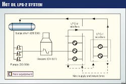
The hot-oil system (Fig. 4) has two subsystems:
- Two heaters constitute the LPG-2 system with a design capacity of 86.5 MMBTU/hr each, supplying the reboiler requirements of the LPG-1 and LPG-2 plants.
- The other subsystem has a heater with a capacity of 132 MMBTU/hr, which supplies the hot-oil requirements to the LPG-3 plant reboilers. Both systems have been designed to heat the oil to 570? F. but currently heat it only to 510? F.
All of the reboilers were simulated under the new conditions to determine the newly required hot-oil flow rate. This simulation led to the conclusion that the systems operating at 510° F. would be unable to achieve the new requirements.
The reboilers were again evaluated under the hot-oil design temperature of 570° F. The LPG-2 subsystem ought to heat the oil to 570° F. and the LPG-3 sub-system to 550° F. to achieve the new reboiler requirements.
The hydraulic system evaluation of the LPG-2 subsystem determined that it would be necessary to install new supply and return lines (Fig. 4).
Additionally, the hot-oil pumps of LPG-2 should be replaced because of wear and obsolescence.
Actions
(Table 5 at right)
- The simulations, then, indicated the following major actions:
- To process the new NGL production in the LPG-1 plant, modifying the depropanizer-tower (T-5A) operating conditions is cheaper than replacing it.
- To process butane flow rate increase, replacing the depropanizer tower (D8-0304) is less costly than modifying operating conditions and re-traying.
- LPG-1 and LPG-2 plants will be able to process the additional NGL production only if tower operating conditions are modified, a refrigerant condenser is installed in the depropanizer (T-5A) and an air-cooled condenser is installed in the debutanizer (D8-506), and the six reflux pumps are replaced.
- LPG-3 plant will be able to handle the butanes coming from LPG-1 and LPG-2 plants (14,750 b/d) and up to 6,700 b/d from the future LPG-6 only if some products` specifications are modified and the depropanizer tower (D8-0304) is replaced.
- Lowering the fractionation towers` operating pressures along with the vapor and liquid loads as well, improving tray hydraulics. That increases the key components` relative volatility, making the separation easier and reducing the heat duty requirements.
- The LPG complex cooling water and hot-oil systems could conform to the new process requirements only if the operating conditions are modified, some new piping is installed, and the hot-oil pumps in the LPG-2 plant are replaced.
- Process Design Manual, Pdvsa, 1996.
- Gas Conditioning and Processing (Vols. 1 and 2), John M. Campbell, Campbell Petroleum Series, 1990.
The Author
Lilia Castro Morín is a process design engineer in the exploration and production division of Petróleos de Venezuela, S.A. (Pdvsa. Her work has included evaluation, optimization and elaboration of process basic design specifications of NGL extraction, fractionation, and gas compression facilities. She has been working with Pdvsa since 1991, when she graduated with a degree in Mechanical Engineering from Simón Bolívar University in Caracas, Venezuela.
