Chicago Develops Commercial Hydrogen Bus Fleet
A Chicago Transit Authority (CTA) project has demonstrated that the industrial gas industry can design and construct central hydrogen fueling stations for fleet applications.
The system is based on liquid hydrogen and high-pressure cryogenic pump technology, modified for fueling requirements.
Theoretically, the hydrogen fuel cell is more efficient than the diesel engine. The hydrogen fuel cell has an efficiency of about 40% while diesel-engine efficiencies are 25-32%.
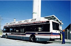
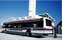
The Chicago fleet`s hydrogen source is based upon delivered hydrogen. This first-of-a-kind hydrogen fueling station has supported transit operations of three fuel cell city buses in Chicago since 1997.
Fuel-cell vehicles (FCVs) that use hydrocarbon fuels require on-board reformers to convert the fuels to a hydrogen-rich gas. The use of hydrogen as the fuel simplifies the vehicle design and provides greater fuel efficiency and environmental benefits.
For the vast market of personal FCVs, however, there is a strong preference to use existing liquid fuel infrastructure. Various companies are developing on-board fuel reformers to generate a hydrogen-rich gas from fuels such as methanol and gasoline.
According to Yazeed Khayyat, manager of alternative fuels and environmental technology at the CTA, the CTA plans to evaluate the performance of the new hydrogen-fueled buses through March 2000. Based on data thus far, Khayyat indicated a high degree of confidence in fuel-cell technology for transit applications.
The fuel range on each bus is 250-300 miles, which is comparable to diesel. Each bus has a storage capacity of 20,000 standard cu ft at 3,600 psig.
To date, the CTA has contributed about $10 million to the project through grants from the Federal Transit Administration, the Congestion Mitigation & Air Quality (CMAQ) program, and state matching funds. This number accounts for research and development, the fueling facility, the three buses, garage modification, initial fuel costs, maintenance, support, and operation. Because much of this cost was spent developing the optimal bus configuration for road use, this number cannot be used to estimate the cost of an additional bus to the fleet.
The decision to purchase more buses, said Khayyat, would depend on two factors. First, costs associated with using the hydrogen fuel-cell buses must be economically feasible. Second, fuel-cell manufacturers must be capable of meeting the production demand for a fleet of buses for the CTA.
Hydrogen vs. liquid hydrocarbons
The proton exchange membrane (PEM) fuel cells currently being developed need hydrogen as a fuel. FCV developers can either develop a hydrogen fuel supply infrastructure or on-board fuel reformers that use the existing liquid hydrocarbon fuel infrastructure.
Although the direct hydrogen fuel option entails building a new fuel infrastructure, it vastly simplifies the design of the FCV and leads to a truly zero emission vehicle (ZEV). Also, it enables the implementation of long-term strategies, such as carbon dioxide capture and the use of renewable energy in transportation with hydrogen as the carrier.
The recovery of carbon dioxide is practiced today by some large central hydrogen plants in geographies where there is market demand for food or petroleum tertiary recovery applications.
Hydrogen storage onboard a vehicle, however, is more difficult than that of simple liquid fuel systems. To provide a vehicle with sufficient range, hydrogen needs to be stored as a liquid at -423° F., as compressed gas at 3,600 psi or higher, or reversibly adsorbed on lightweight carbon materials.
Currently, compressed hydrogen is the most readily implemented option due to its similarities to the growing compressed natural gas fuel infrastructure.
Liquid hydrogen fueling needs further development to make it a fully automated process for the mass market. Another drawback for liquid hydrogen use is inevitable boil-off losses associated with long periods of non use of vehicles.
Some technical breakthroughs are required to make carbon adsorbents a viable alternative for hydrogen storage.
Well developed gasoline and diesel infrastructures in the developed countries make on-board fuel reforming an attractive option. The vehicle design for on-board fuel reforming is much more complex and challenging than for direct hydrogen vehicles. Highly compact fuel reformers need to be developed.
These devices need to start up quickly, have rapid response to load changes, and have very high reliability. Also, the fuel reformers need to be significantly less expensive than conventional reformers, since they will be idle much of the time and thus represent a very poor utilization of capital. In addition, significant capital investments will be required in refinery modifications to produce very low sulfur gasolines compatible with fuel cells.
Technical and economic studies1 2 suggest that fuel reformers will add more weight to the vehicle and reduce fuel-cell, peak-power output. To make up for this lack of power, larger fuel cells and larger motors are required to obtain the same performance (in terms of drive train power to vehicle weight ratio).
The resulting extra weight then requires larger drive train components, further compounding the weight problem. Thus, for the same level of performance, hydrogen FCVs will be simpler in design, lighter in weight, more energy efficient, and lower cost than those with onboard fuel reformers.
Fuel-station design
The hydrogen fuel station has been in service since September 1997, and is now routinely fueling the three fuel-cell buses on a daily basis in Chicago.
The CTA`s demonstration fleet of three PEM fuel-cell buses operate on hydrogen gas stored at 3,600 psi in roof-mounted lightweight composite tanks. The station has facilities for receiving, storing, processing, and transferring hydrogen.
The fuel transfer to the bus is via a fully automated dispenser. The fueling is performed by CTA personnel, with training in the safe handling of hydrogen.
The station can fuel three buses within a 2-hr period. This requires a maximum delivery capacity of 80,000 standard cu ft/hr (scfh) to achieve a settled storage pressure of 3,600 psi at ambient conditions ranging from 0 to 100° F. Each bus consumes about 15,000-20,000 scfd of hydrogen.
For this location, it proved to be most economical to deliver liquid hydrogen, and to use cryogenic liquid pumps to achieve the high storage pressure needed.
Liquid hydrogen is transported to Chicago in cryogenic 15,000-gal liquid tanker trailers from a plant located about 300 miles away. The hydrogen is stored on site in a double walled vacuum insulated tank with a liquid capacity of 9,000 gal.
The cryogenic pump moves liquid hydrogen from the storage tank pressure of about 150 psi through a vaporizer to refuel the buses with gaseous hydrogen at 3,600 psi. This pump requires less energy than needed to compress gaseous hydrogen to the same pressure.
With high pressure gas-buffer storage, it is possible to initiate bus fueling immediately while the cryogenic compressor is still cooling down, preparing to pump hydrogen to the bus.
Fig. 2 is a schematic of the fuel station, which comprises two major systems:
* A fuel preparation system to receive, store, compress, and vaporize the hydrogen
* A fuel transfer system to transfer the high-pressure hydrogen to the tanks onboard the buses.
The station design is based on a patented Cryogenic Hydrogen Compressor (CHC),3 which has wide applications for high-pressure hydrogen supply in the chemical industry. A modified design was developed for the fuel station application and designated CHC-6000.
The compressor package consists of a single-stage, reciprocating, positive-displacement pump unit, driven by a 30-kw ac motor.
Safety was given the highest priority in both the design and operation of the fuel station. The three primary hazards which were addressed in the design were fire, over pressurization of the storage tanks on the bus, and movement of the bus while refueling.
System operation
The CHC-6000 refueling system is normally in a "standby" mode where it is ready to begin filling buses immediately. In this mode, the storage tube and tank pressures are monitored continuously by the PLC within the CHC system control panel.
Once a bus-fueling sequence is initiated, a signal from the fuel-transfer system control panel starts a timed process to cool the CHC-6000 compressor to operating temperatures.
While this is happening, the bus is being filled from the bank of high pressure gaseous storage tubes. Once pressures have equalized between the storage tubes and the bus tanks, an automatic valve is shut to isolate the storage tubes.
After the cooldown period, the CHC-6000 starts and begins to fill the bus directly. Typically, the bus can be completely filled within 15-20 min, depending upon the starting pressure of the bus. Once the bus is filled, the isolation valve is reopened and the storage tubes refilled in 5-10 min so that it is available for the next bus.
The single CHC pump system is capable of filling 2-3 buses per hour on a continuous basis. It takes about 2 hr, however, to move all three vehicles into place, fuel them, and move them out again because there is only one fueling bay in Chicago.
On-site production option
The adaptation of existing liquid hydrogen delivery technology for hydrogen fueling will be largely limited to North America and some parts of Europe, where liquid hydrogen is readily available.
In most of the rest of the world, liquid hydrogen is not commercially available. In these areas the hydrogen infrastructure will develop via small-scale, hydrogen-generation units at the fuel station, which will produce hydrogen from fuels such as natural gas, methanol, and propane.
Currently, commercial steam-methane reformers (SMRs) for on-site hydrogen production are economic at a scale above about 1 MMscfd (2.5 metric tons/day). Recent developments in hydrogen generators, however, driven by the needs of stationary fuel-cell power plants, are offering the real possibility that distributed hydrogen generation could be competitive with centrally produced hydrogen in sizes as small as 3,500 scfh.
By putting a larger hydrogen generator at the fuel station instead of thousands of fuel reformers on individual vehicles, a greater utilization factor is achieved. Also, problems associated with FCVs, such as rapid start-up and rapid response to transients, are eliminated.
Operating these fuel generators on natural gas can take advantage of the widespread network of natural gas pipelines. Also, methanol reformers appear relatively simple, and the availability of methanol is worldwide.
Studies by others have shown that the investment costs per vehicle for these small stationary hydrogen-fueling appliances would most likely be less than the current annual cost per vehicle to maintain or add new gasoline infrastructure or onboard liquid fuel reformers.4
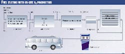
To implement a hydrogen-fuel station based on these on-site fuel reformers, additional gas purification, compression, storage, and dispensing equipment will be required (Fig. 3). These small generators afford a pathway to gradually build the hydrogen supply infrastructure in step with the growth of FCV sales.
Thus, the industry can closely match the supply and demand for hydrogen in the early years of the commercialization of FCV without the risk of large amounts of capital needed for large-scale hydrogen production facilities.
References
- Thomas, C.E., James, B.D., and Lomax, F.D. Jr., "Market Penetration Scenarios for Fuel Cell Vehicles," 8th Annual U.S. Hydrogen Meeting Proceedings, National Hydrogen Association, Washington, D. C., March 1997, pp. 137-69.
- Ogden, J., Steinbugler, M., and Kreutz, T., "Hydrogen as a Fuel for Fuel Cell Vehicles-A Technical and Economic Comparison," 8th Annual U.S. Hydrogen Meeting Proceedings, National Hydrogen Association, Washington, D.C., March 1997, p. 469-506.
- Schuck, T.W., and VanOmmeren, J., U.S. Patent 5,243,821, Sept. 14,1993, "Method and Apparatus for Delivering a Continuous Quantity of Gas over a Wide range of Flow Rates."
- Thomas, C.E., Kuhn, I.F., James, B.D., Lomax, F.D. Jr., and Baum, G.N., "Affordable Hydrogen Supply Pathway for Fuel Cell Vehicles," World Car Conference, Paper 97WCC061, Riverside, Calif., Jan. 21, 1997.
The Author
Venki Raman is manager of global hydrogen applications for Air Products & Chemicals Inc. He develops new application and production technologies for hydrogen. He is responsible for the company`s new initiatives for transportation and clean energy production.
Raman has participated in several hydrogen transportation demonstration projects, the most recent in Chicago. He served as chairman of the National Hydrogen Association from 1997 to 1999.
Raman holds a PhD in chemical engineering from the University of Washington, Seattle.


