Inland barge to allow cluster drilling in Nigeria
A unique shallow-water drilling barge designed for sequential well drilling should commence operations in September in the Tunu field of Nigeria. "The barge will allow us to remain in place and drill a cluster of six wells without moving," says Herman Schellstede, president and owner of Herman J. Schellstede & Associates Inc.
The concept for Parker Drilling Co.'s Rig 75 began in mid-1996 when Shell Petroleum Development Co. began tackling economic, environmental, and security issues involved in moving barge drilling rigs in the swamps of Nigeria.
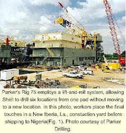
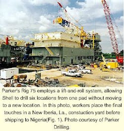
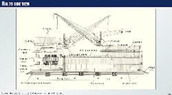
Over the next 3 years, Shell, Parker, Herman J. Schellstede & Associates, and Oil Barges Inc. (OBI) worked together to design and build the rig, resulting in delivery last July (Fig. 1). "This is the first drilling barge since the 1980s to be designed from a clean sheet of paper," Schellstede says.
Innovative features include:
- A skiddable substructure
- The ability to move without lowering the mast or laying down drill pipe
- The ability to perform drilling operations on one location while carrying out completion operations on another
- A network of sensors, consoles, and computers that provide real-time drilling information to various locations on the rig.
Skidding system
To move from one well to another, the rig employs a lift-and-roll system, developed by Southern Technology & Services Inc. The hydraulic power system produces longitudinal and transverse translations resulting in 8-ft displacements between each of six well centers.
"We believe that 6 days/well can be saved or 30 days per set of 6 wells with this system," said Mike Lomax, international operations manager for Parker.
Prior to the lift-and-roll system, traditional systems used enormous rams without rollers that placed tremendous and dangerous forces on the structure. "But by placing the substructure on rollers, we were able to reduce the coefficient of friction," Schellstede says.
The lift-and-roll procedure works as follows:
- A series of jacks lift the substructure 3/4 in. above the base.
- Horizontal rams push the substructure 91/4 in. in the desired direction.
- Once the horizontal distance has been reached, the structure is lowered to the base, completing the cycle.
- Steps 1-3 repeat until the rotary table is placed over the next well spot.
Schellstede says this technology evolved from skidding mechanisms used on platform rigs.
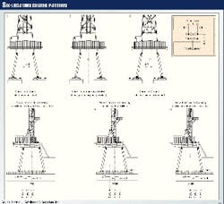
Fig. 2 shows the general arrangement of the substructure used to accommodate the six-location cluster pattern. Transversely, the substructure can translate 4 ft to either side of the centerline (Fig. 2, stern views 1-3), providing slots for two well locations in this direction. For example, crew members can skid the rig from Well 1 to Well 4 in Row A.
Longitudinally, however, the substructure can be moved a distance of 16 ft with three wells drilled in the opposing direction (Fig. 2, view 4-6). For example, crew members can skid the rig from Well 6 (Row C) to Well 5 (Row B) to Well 4 (Row A).
Ema Haq, project engineer for Parker, says cycle time will be shortened because the substructure can be skidded with pipe in the mast. This capability eliminates the time-consuming procedure of laying down drill pipe, lowering the mast, moving the rig, then raising the mast and picking up drill pipe between wells.
Also, the ability to run two mud systems simultaneously, including water and oil-based drilling muds, should add further cost and time savings, Lomax says.
Lots of room
The internal structure of the drilling vessel consists of tubular columns that extend from the barge deck to the hull. "These columns are placed in concert with the movement of the substructure.
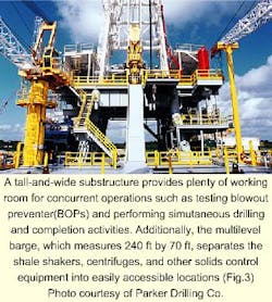
The upper-most substructure support, containing 18 platens that connect to the structure of the vessel, have been optically aligned to provide an extremely flat work surface. Additionally, "The substructure is twice as high as a standard barge," with 58 ft between the drill floor and top of the barge.
Thus, the substructure provides a very open and simple design that carries the inherent strength of tubular cross sections while allowing open access for the handling of the protective deck, jacket, well heads, and blowout preventer (BOP) equipment (Figs. 3 and 4).
For example, the substructure design allows for storage and stack up of both BOPs in one location (see accompanying box for rig specifications). Additionally, the BOPs can be tested in parallel with other operations, permitting faster nipple up and less flat time.
Protected work site
A jacket protects all six wells, sized to assist with the placement of the vessel as it is ballasted. Additionally, Rig 75 provides two protective barriers for the safety of the workers and equipment, in particular, the flow-line valves and christmas trees on live wells.
First, the drill floor has been reinforced to accept major point loads avoiding any punch through by tubulars or dropping of the BOP.
Second, the well bay area contains a protective deck that is fitted into the jacket with mating legs, providing a secondary strengthened deck that is also impervious to tubular punch through or BOP turnover.
Well security is also improved as the six-well structure can be fenced, guarded, and secured as easily as single wells could be in the past.
Pollution control
"Similar to barges operating in Louisiana, we equipped Rig 75 for zero discharge," Schellstede says. For example, the 20 x 50-ft keyway at the stern of the vessel comes equipped with a pollution gate, providing effluent control in the well-bay area (Fig. 5). "Not even rain water will escape the vessel," he said.
Additional pollution-control equipment includes drip pans under the rotary table.
Benefits from the six-spot well pad include a reduced environmental impact because location preparation work will be reduced to one-sixth.
Drilling instrumentation
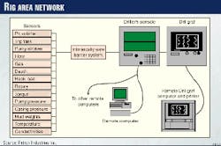
A network of sensors, consoles, and computers will provide the driller, company man, mud engineers, and other key personnel with information about drilling conditions at various points along the rig (Fig. 6).
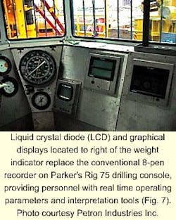
For example, an alphanumeric LCD display, developed by Petron Industries Inc., displays sensor information such as depth, hook load, torque, and rotary speed at the driller's console (Fig. 7).
Additionally, a rig-floor graphical display (see box), also installed at the drilling console, replaces the typical 8-pen chart recorder. Information is graphically provided on four screen pages that represent tripping, circulating, and two drilling formats. Comments can be added with historical data automatically stored on a continuous basis.
The front end of the system, provided through a PC-based workstation installed in the company representative's office, includes enhanced graphical representations used to establish certain trends and values while providing a management system for data acquisition.
For example, customizable screens can indicate such developing problems as drill-pipe washouts, doglegs, bit wear, and well-control situations.
Additional consoles and workstations can be installed around the rig as needed. Finally, a gas-analysis unit, permanently installed in the mud engineer's cabin, provides continuous total hydrocarbon and chromatograph analysis.
