Research rig, diverse geologic conditions, provide unique testing environment
Dean E. Gaddy
Drilling Editor
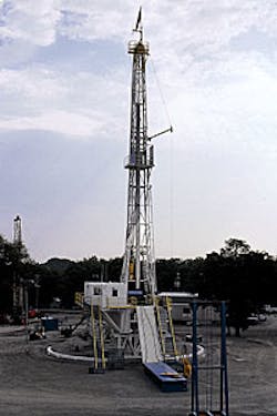
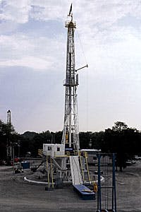
Last August, Amoco Corp. dedicated Test Rig No. 11 (Fig. 1) at its test site in Catoosa, Okla., replacing its predecessor, a converted snubbing unit affectionately called the "Blue Rig."
Built in 1986 to develop a high-speed drilling system, Amoco's Drilling Technology Test Facility (DTTF), located 18 miles northeast of Tulsa, consists of a drilling and completions test facility, drilling-hydraulics test loop, solids-control test facility, and drilling-simulator laboratory rig.
Since then, the facilities have developed several breakthrough technologies, including antiwhirl polycrystalline diamond-compact bits; wire line-retrievable, continuous-coring systems; short-radius, horizontal recompletion systems; and rotary-steerable tools.
Until recently, Amoco used the test facilities almost exclusively for internal research projects. However, faced with budget cuts and the need for the facility to become self-sufficient, Amoco opened the DTTF to outside operators and service companies. According to Ron Bray, technology director for the DTTF, "Over 80% of our work is done for companies other than Amoco."
Current customers include Schlumberger Inc., Smith Tool Co., Polybore Services Inc., Security DBS, and Amoco. In order to protect the proprietary work of each customer, the rig is cordoned off so no unauthorized visitors are allowed near the work activities. Rig crews are provided through an alliance with Parker Drilling Co. and include five crew members and a toolpusher. The DTTF also has a machine and welding facility available for remedial work.
Pivoting rail system
According to Scott Lovin, technical systems specialist for Parker Drilling Co., Rig No. 11 uses a pivoting rail system that allows it to skid from location-to-location across a semicircular path ( Fig. 2 [62,429 bytes]). "Instead of moving in 2 to 3 days, No. 11 will be able to move in 2 to 3 hr. When it comes time to move, we will simply pull the blowout preventer and riser, raise the V-door and stairs, then skid the rig to the next location" using either the draw works or hydraulic cylinders.Rig No. 11 includes many enhanced features over its predecessor. "We should be able to trip 75% faster than the Blue Rig. For example, we now have the capability to drill 60-ft stands with the use of an auxiliary mousehole," said Joey Turney Sr., toolpusher for Parker. In addition, the mud pits and pumps are set up in a stationary location, thereby eliminating most of the time needed to rig up the rig's fluids-control equipment.
As many as 11 surface locations, spaced about 9.5 ft apart, will be drilled across the template. Each location will begin with a surface hole drilled, cased, and cemented to about 165 ft. Surface casing sizes include 133/8, 95/8, or 7-in. strings. The rig will then reenter the parent surface hole and kick off at a slight angle away from the initial starting point, allowing for as many as 9 to 11 splays from a single surface location.
"These well configurations may include an S-shape that returns to vertical in addition to directional, horizontal, and even multilateral well patterns, depending on the customers' needs (Fig. 3 [93,769 bytes])," Lovin said. He estimates it will take 5-6 years before an additional template is needed. However, this estimate depends on the nature and configuration of the well designs. For example, if a customer arranges exclusive rights to a surface hole, the total number of wells drilled from the template could be less than anticipated.
Unique geology
"What makes this site unique is the variety of formations close to the surface," Lovin added. The stratigraphy of the Catoosa test site includes a 1,200-ft Pennsylvanian section, a 400-ft Devonian/Mississippian section, and a 2,300-ft Cambrian/Ordivician section. Most of the testing activity has been conducted in the Pennsylvanian and Mississippian sections, although two wells were drilled into the granite basement at 3,056 ft.The interval between surface and 2,000 ft has been extensively cored and logged for purposes of calibration and correlation. Thus, the test facility allows direct field testing of drill bits, drilling fluids, and downhole tools across a diverse sequence of lithologies including limestone, sandstone, shale, and dolomite.
The exact boundary for each lithologic change is known, so it is easy to correlate product performance changes.
Equipment
Rig No. 11 is equipped with two drillstrings consisting of light-weight, 41/2-in. aluminum drill pipe and 27/8-in. steel drill pipe for smaller holes. Aluminum drill pipe was chosen because its lower modulus provides twist and vibration properties similar to that of a longer string of steel pipe.The drilling rig has a 107-ft mast and two levels of box substructures stacked one atop another for an RKB (rig kelly bushing) height of 22 ft. The power swivel is a hydraulically driven Venturetech VK-150 capable of 12,000 ft-lb at 250 rpm. The swivel is carriage mounted and restrained by a torque track system. The drilling rig's two rotary tables have 171/2 and 271/2-in. slip bowls.
The hoisting system, capable of handling normal drilling loads to 200,000 lb, consists of a National T-20 drawworks modified to accept hydraulically driven motors. According to Lovin, "The motors turn in both directions. Thus, they can slow, park, and brake the drillstring load without help from drum brakes or the hydromatic."
For precise weight-on-bit (WOB) control, Test Rig No. 11 uses a servo-controlled, hydraulically actuated cylinder as an autodriller. This WOB cylinder also allows the rig to duplicate specific testing conditions such as offshore wave action.
The 330-bbl active mud system consists of six tanks. The primary rig pump is a Skytop Brewster B1100T triplex capable of pumping 130 to 700 gpm. For testing low flow rates, the facility include several smaller pumps, including a Haliburton HT-150, Haliburton HT-400, Gardner Denver PW-3H, FMC M1626AB, and a Gardner Denver TEE.
The solids-control system consists of two low-profile, ultra-fine screen shakers, a set of 12 Amoco-designed hydrocyclones, and a Sharples PM 20,000 centrifuge. A standard mud hopper and suction/mixer tank is used to mix mud with a charge pump feeding the primary rig pump.
Data acquisition
The data-acquisition module, a climate-controlled structure cantilevered from the top substructure, allows the data-collection equipment to be located on the rig floor while keeping the personnel and electronics safe. Drilling information is measured with precision sensors and associated signal-conditioning equipment installed throughout the rig. This data-collection laboratory records hook load, WOB, rotary speed, rotary torque, hoist position, bit depth, pump pressure, mud flow rate, and drillstring axial accelerations. The system captures information concerning the performance of:- Drill bits
- Logging and measurement-while-drilling tools
- Direction and horizontal drilling tools
- Vibrational subs, underreamers, stabilizers, and other bottom hole assembly tools
- Mud systems
- Cementing procedures
- Coring
- Logging and seismic tools.
Test loop, solids control
The test site also provides a drilling hydraulics test loop joined with all the pipe sections, valve manifolds, pump, tankage, and instrumentation necessary to control and measure pressure drop, mass flow rate, and temperature.This full-scale test loop is designed to investigate the hydraulic behavior of single-phase fluids for all types of drilling fluids from water to oil-based mud to cement.
Research through the use of the test loop has provided accurate fluid models concerning:
- Tool-joint pressure losses
- Pipe-pressure losses in smooth and rough pipe
- Concentric annulus with smooth and rough pipe
- Eccentric annulus with smooth and rough pipe
- Laminar/turbulent transition in pipe, concentric and eccentric annulus.
Workover rig
In addition, the Catoosa test site includes a workover rig primarily dedicated to drilling slim hole (37/8 in., 61/8 in.), short-radius (30-90 ft) wells. The Chicago-Pneumatic workover rig has a Gardner Denver pump capable of pumping 150 gpm at 1,100 psi.The rig is rated to 2,000 ft and 40,000 lb. The drillstring normally consists of 27/8-in. S135 drill pipe and 31/8-in drill collars. Composite and steel articulated drill pipe is also used to drill the short-radius curves.
Copyright 1998 Oil & Gas Journal. All Rights Reserved.

