Intelligent fuzzy system helps offshore platform start-up
Intelligent systems with a fuzzy controller can play an important role in controlling and managing start-ups of offshore facilities.
This technology has been instrumental in operations on the Petrèleo Brasileiro SA (Petrobras) semisubmersible production unit P-19, which has been in service since June 1999 in the Campos basin, off Brazil.
Intelligent systems have many heuristic rules for automating start-up procedures. These rules include opening many on-off valves while simultaneously monitoring process variables. A fuzzy controller, on the other hand, is used to optimize the opening of oil wells so as to minimize the start-up time and to respect many real-time process constraints.
Improved information availability combined with automation of some tasks can result in faster start-ups and provide such benefits as reduced spurious shutdowns during the start-up procedure.
These tools also provide a way for training new operators and improving operator performance as growing process complexity and pressure of safety, health, quality, and environmental issues complicate an operator's life, which can become overloaded.1
Automatic systems
Petrobras has established many programs for optimizing offshore facility operations, including one for developing intelligent automatic systems. These systems try to encapsulate knowledge of the process and its operating behavior to guide operators during, for example, the start-up of a facility after a shutdown caused by signals from an interlocked system.
This article describes the integration of an intelligent system with a fuzzy controller used on P-19. References 2 and 3 discuss other aspects of this work.
These automatic systems can provide smoother and more economic operations, fewer operating errors, fewer product rejects, and also less possible damage to personnel, equipment, and environment.
Processing facility
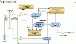
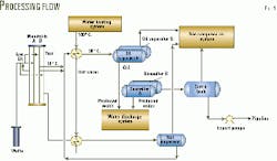
P-19 operates in 770-m water about 105 km from Rio de Janeiro. Oil processing on the facility consists of three major components: crude oil separation, water injection, and gas-lift compression (Fig. 1).
After crude oil is separated, the components are handled as follows:
- Oil enters a pipeline.
- Gas provides fuel for the power generation, gas for gas lift, with the excess gas being exported.
- Water, after being cleaned, is discharged overboard.
The gas-lift facility includes a treatment plant, compressors, knockout drums, and gas coolers to recycle the gas. Components of the water-injection facility include filtration, deaeration, chemical injection, and high-pressure water injection pumps.
Control architecture
The intelligent fuzzy system (IFS) is embedded in an intelligent start-up system (ISS) that, as the name implies, helps the operator start up a processing facility. In its final phase, the start-up system starts the fuzzy system for controlling the production valve on each well.
The ISS supervises the facility for 2 hr after completion of the start-up. It then stops, while the fuzzy system continues to control the production valves for as long as the operator wishes.
The start-up system is a set of software modules that includes:
- Intelligent fuzzy system class definitions (fuzzy-logic module).
- Start-up system class definitions (start-up definitions module).
- Module containing the plant-specific implementation for the start-up system and for the fuzzy system (plant start-up module).
- Other auxiliary modules, such as the equipment class definitions (equipment module) and the plant model implementation (plant module).
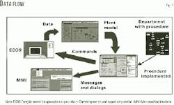
Each application in this implementation module set (containing object instances) requires a definition module (containing object classes, including their methods), and a communication bridge that links the start-up system to the company's ECOS (estação central operação e supervisão or central operation and supervisory station) architecture (Fig. 2). Some modules are shared with other applications.4 5
The ECOS architecture is a set of software and hardware specifications used for plant automation within the company. The supervisor software reads data from the instruments and sends data to the actuators through programmable logic controllers (PLCs).
The bridge is started by one of the start-up system modules, the interface module, and is controlled by the communication module.
Implementation
Pretrobras needed about 12 months to implement the application in an object-oriented expert system environment.
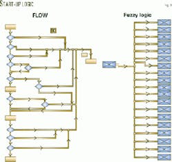
The start-up system is built over a flowchart implementation called flow (left side of Fig. 3). The flow portion is a set of processing blocks, step blocks (rectangular blocks with one input and one output) or decision blocks (class derived from step block, shown as diamonds with one input and two outputs). A procedure is associated with each processing block.
A mechanism (processing block methods and flow methods) controls the sequencing from one block to the next, starts each associated procedure, and associates the flow execution with a particular execution workspace (a sequence).
Procedures associated with decision blocks return a value, either true or false, so that the mechanism knows which block connected to its outputs is the next one. Several flows can be executed at the same time and in more than one execution workspace. It is also possible to abort the execution of the flows within a selected execution workspace.
This flowchart implementation allows the petroleum engineer to model the start-up procedure abstractly, thus allowing the software developer, maybe the petroleum engineer, to implement and organize the procedures in a somewhat natural way, step by step.
The fuzzy system is implemented as a set of instances from four classes of data:
- Input process variables.
- Connected input linguistic variables (Fig. 3, right side).
- Output linguistic variables.
- Output numerical variable.
The input linguistic variable values are turned fuzzy in the first part of the process, after which the activation for each input linguistic variable is calculated. This set of values is the fuzzy equivalent for the input value.
Then, an activation value is calculated for the output linguistic variables, and a procedure is associated to each output linguistic variable for calculating its activation value.
Finally, the output numerical value is calculated, also by a procedure associated with the output numerical variable.
The output is used to control the opening of the wells. The inputs are fluid level, oil temperature, surge level, and surge pressure of each production vessel.
Intelligent start-up system
An offshore unit has many interlocked systems that can shut down the platform for safety reasons. The main objective of the ISS is to guide the operators so that they can start or restart the processing facility in the least time after a shutdown.
This system will automatically do many tasks, but the operators can continuously control, supervise, and change the steps in the start-up procedure. Petrobras considers the operators as an integral part of the automation system; therefore, the ISS only will act in the process after receiving an acknowledgment from the operator.
The start-up system takes care of the main processing systems, such as for oil separation, oil export, gas-lift, gas export, and water injection.
For all these systems, the start-up strategy takes into account all operational, safety, and environmental aspects, with flowcharts organizing this knowledge. Flowchart models have the advantage of containing a wealth of deep and practical knowledge that can be easily followed in an automatic system during all start-up situations.
A generic start-up procedure for an offshore oil producing facility consists of the following steps:
- Verify auxiliary systems.
- Open on-off valves of the separation systems.
- Open the subsea wellhead valves.
- Start the oil export pumps.
- Open choke valves on the wells to begin oil production.
The auxiliary system verification process goes through a checklist of all systems and equipment required for the start-up. This verification process monitors key parameters and advises the operators, if necessary.
The second critical task executed by the start-up system is to automate the reset of many on-off valves. On P-19, the operators have to open and supervise more than 40 on-off valves before going to a new phase in the start-up procedure.
The greatest problem with this task is that different sensors interlock many of these valves, so that the operator must remember to retry opening these valves in the next phase of the procedure.
If the work overloads the operators, the interlocked system could trip the platform and force the operators to begin the start-up process again.
The ISS helps the operator perform these repetitive tasks by automating the reset, monitoring valve positions, and automatically doing the resetting when necessary. With this automatic system, the operators can focus on other safety, environmental, and quality constraints, reducing the overall time to start-up the platform.
In the next main step in the start-up procedure, the ISS automatically opens all the wells and verifies that they are open.
Once this is completed, all choke valves are opened and oil and gas production begins.
The industry typically opens the choke valves of each well continuously until the valve reaches a desired opening. The main problem in automating this procedure is the need to monitor many proportional integral derivative (PID) controllers in the processing unit, such as the level controllers on the separators and surge tank.
To solve this problem and improve the operation, the start-up system uses a fuzzy controller for optimizing the opening of choke valves. This fuzzy controller can control nonlinear multivariable systems in the presence of real-time constraints.6-8
Fuzzy logic
The concept of fuzzy sets is based on the idea of vagueness or sets without sharp boundaries. It was introduced to describe systems that are too complex or too ill defined for precise mathematical analysis.9
Fuzzy logic's major features are the use of linguistic rather than numerical variables and the characterization of relations between variables by fuzzy conditional statements. A relation or function defined on a given universe may be used to describe a fuzzy set. Consider a universe, U, and a fuzzy set, A, defined on U by Equation 1 in the equation box.
The term µA(x) is the degree of membership in A that x possesses. Therefore, a fuzzy set consists of a pair, x and µA(x). The union, intersection, and complement of two fuzzy sets, A and B, can be defined by Equations 2-4.9
In general, the intersection of a fuzzy set with its complement is not empty because it is not a traditional discrete set. Reference 10 contains more detailed information about fuzzy set theory.
Multivariable fuzzy controller
Mandani and Assilian recognized that fuzzy logic provides a means of dealing with uncertainty and they extended the concept to industrial process control, thus, creating a rule-based controller.11 This fuzzy approach assumes that there is qualitative information about the process that remains unused by conventional approaches but which might be very important for good control.12
Using fuzzy logic does not require a mathematical description of the facility's dynamics. Instead, knowledge of the facility is contained in extensive sets of rules (expressed linguistically) that describe the facility's operation. This set of rules is called a fuzzy control algorithm.
A multivariable fuzzy controller can be represented by a set of linguistic rules, such as:
- If (Al(1) and KAn(1)) then Ul(1) and U2(1)K and Um(1).
- If (Al(h) and KAn(h)) then Ul(h) and U2(h)K and Um(h).
Ai are fuzzy sets (such as "high-temperature error"), encompassing the input universe, while fuzzy sets Uj (such as "small variations in the valve") are defined by the output universe.
Also known is that a multivariable system can be represented by m single-output systems.13 In this case, the "if" parts are repeated for each output variable Uj and Equation 5, the control law, is obtained. Equation 6 calculates Rji.
These equations are not unique, however; the "max.-min.' presentation seems to be the most widely accepted and was therefore used.7
Because the intelligent system is operating at a supervision level, the manipulated variables of the fuzzy controller open the choke valves of the wells. Controlled variables considered were each separator's variables (level, temperature, and pressure), surge tank level, and pipeline pressure.
These variables are constraints. Therefore, they are controlled within high or low zone limits. These limits set the boundary on the unit operation and must be respected.
The controller opens and maintains all manipulated variables at their ideal values when the controlled variable constraints are respected. Ideal values are the opening position desired and the speed that the system can manipulate each well (during start-up) as a function of the production requirements and analyses.
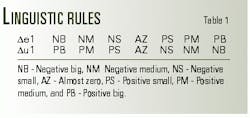
The entries in the table are mnemonics for fuzzy sets. Thus, NB, NM, NS, AZ, PS, PM, and PB correspond to "negative big," "negative medium," "negative small," "almost zero," "positive small," "positive medium," and "positive big," respectively.
Rules for the algorithm are dynamic in that, if the controlled variables are at abnormal levels, then the manipulated variables are adjusted appropriately by incremental changes.
The rule set does not, by any means, exhaust all the possible process states, and it may be considered a "sparse algorithm." In this case, the sampling frequency of the controller is assumed to be once every 10 sec.
Petrobras designed a simulator for testing and tuning the intelligent fuzzy system. The simulated input disturbances used for evaluating the algorithm were based on the typical conditions in the P-19 facility.
A mathematical model of the process first derived an estimation of the fuzzy controller parameters before the controller was finely tuned in the field.
The fuzzy controller's robustness was investigated by changing parameters of the P-19 simulator models and evaluating some cost function.7 Simulation software tested the mathematical model.
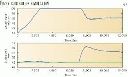
Fig. 4 illustrates how the fuzzy controller works. It shows the fuzzy controller manipulating the choke valves positions to control the surge tank level after a shutdown in two export pumps.
Intelligent system results
The intelligent system has been operating since June 1999 on the P-19 facility. The operation personnel, who have been working with the system ever since, point out the following advantages for P-19:
- Standardized start-up procedures that minimize operational missteps.
- Average gain of 30% in the start-up time because of the automatic opening of 40 on-off valves in parallel. Before system implementation, the operators needed to page through the supervisory system screens to access these 40 valves.
- Friendly interface that allows operators to stop, change, or reconfigure the application, and solve problems at the facility along the start-up sequence. The system shows several messages on the progress of the start-up, and the application helps novice operators to safely do the start-up.
- Individual configuration for each producing well. For example, choke speed and maximum opening are set for each well. In this way, production well start-up complies with the characteristics and constraints of each reservoir, and releases operations personnel from this task.
The system does not follow a strict automation procedure. Instead, it considers many process variables to decide how wells should be aligned and at what speed should they be opened. This approach prevents unexpected interlocks such as when high levels in processing vessels occur because of a shutdown of an export pump.
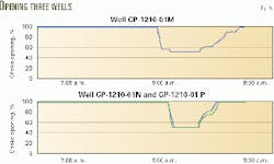
Fig. 5 shows the system opening three production wells (CP-1210-01M, CP-1210-01N. and CP-1210-01P), each at its own speed.
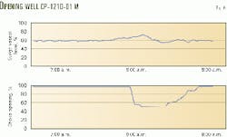
Fig. 6 shows the fuzzy system controlling the choke opening of Well CP-1210-01M as a function of surge vessel level. When the level control of the surge vessel is disturbed, the figure indicates the valve opening process is momentarily decreased.
References
- Lien, K., and Perris, T., "Future directions for cape research perceptions of industrial needs and opportunities," Computer Chemical Engineering, Vol. 20, Supplement, 1996, pp. 1551-57.
- Campos, M., Satuf, E., and Saito, K., "Intelligent System for Start-up of a Petroleum Offshore Platform," ISA Tech 1999, Philadelphia, Pa., Oct. 5-7 1999.
- Campos, M., Satuf, E., and Mesquita, M., Start-up Automation of a Petroleum Offshore Platform, SPE Annual Technical Conference and Exhibition, Dallas, Oct. 1-4, 2000.
- Pochmann, M., Xerez, M. de, Ebecken, N., Kaszkurewicz, E., Teixeira, E., Bhaya, A., and Durao, R., "A Process Fault Detection and Diagnostic Module for Oil Platforms," Fifth Brazilian Petroleum Congress, Brazilian Petroleum Institute (IBP), Rio de Janeiro, 1994.
- Xerez, M., Pinto, R., and Pires, S., "MODIG-A Process Diagnostic Advisory System," SPE Annual Technical Conference and Exhibition, Dallas, Oct. 1-4, 2000.
- Kosko, B., Neural Networks and Fuzzy Systems, Prentice Hall, Englewood Cliffs, 1992.
- Harris, C.J., Moore, C.G., and Brown, M., Intelligent control-Aspects of fuzzy logic and neural nets, World Scientific Publishing, 1993.
- Mendel, J.M., "Fuzzy logic systems for engineering: A tutorial," Proceedings of the IEEE, Vol. 83, No. 3, 1995, pp. 345-77.
- Zadeh L.A., "Fuzzy Sets," Information and Control, Vol. 8, 1965, pp. 338-53.
- Dubois, D., and Prade, H., Fuzzy sets and systems: Theory and Applications, Academic Press, New York, 1980.
- Mandani, E.H., and Assilian, S., "An experiment in linguistic synthesis with a fuzzy logic controller," International Journal of Man-Machine Studies, Vol. 7, 1975, pp. 1-13.
- Tong, R.M., Beck, M.B., and Latten, A., "Fuzzy control of the activated sludge wastewater treatment process," Automatica, Vol. 16, 1980, pp. 659-701.
- Gegov, A.E., and Frank, P.M., "Decentralized fuzzy control of multivariable systems by active decomposition of control laws," International Journal of Control, Vol. 62, No. 4, 1995, pp. 781-98.
