Lousiana refinery retrofitted entirely with fieldbus
The Calcasieu refinery at Lake Charles, La., recently replaced its pneumatic control system with a Foundation fieldbus system that uses the PlantWeb open field-based architecture.
Installation took less time than the alternatives considered, and plant operations improved through reduced product losses and higher throughput.
Calcasieu refinery
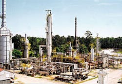
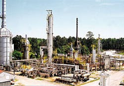
The Calcasieu plant (Fig. 1) is a topping refinery on the Calcasieu River estuary about 7 miles southwest of Lake Charles. Originally built in 1977 and later enlarged to a capacity of 22,000 b/d, it now employs about 33 people.
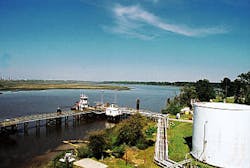
Sweet Louisiana crude produced within 100 miles is processed to yield stabilized naphtha, kerosine of jet fuel "A" quality, diesel fuel, olefin-rich LPG, and reduced crude. The adjacent tank farm has 17 tanks with a total capacity of nearly 810,000 bbl. Crude and products are mainly transported by barges at two docks (Fig. 2).
Some naphtha, however, is delivered by a 5 mile, 16-in. pipeline to a refinery across the river. In addition, there are five tank truck stations for receiving crude and delivering kerosine, diesel fuel, and LPG.
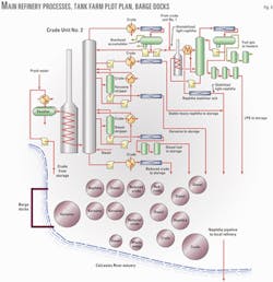
By 1999, the Calcasieu refinery's capacity had been gradually upgraded to about 15,000 b/d. At that time, the main processing facilities (Fig. 3) were a single atmospheric crude tower known as Unit No. 2 and a naphtha stabilizer unit that removed LPG from a light fraction in the naphtha product.
The original 5,000-b/d Crude Unit No. 1-nearly identical to Unit No. 2 except for size-had been decommissioned in 1980. All of its components, except the idle tower, strippers, and accumulator, had been incorporated into Unit No. 2 to increase its capacity and efficiency.
Calcasieu control system
This plant was probably one of the last refineries built with pneumatic controls before the long-established style was superseded by electronic analog instruments and then later by distributed control systems (DCS). One wall in the control room was devoted to a conventional pneumatic panel featuring 1970s-era indicators, controllers, and strip-chart recorders.
Thermocouples performed temperature measurement. Burner-management systems for the gas-fired heaters were based on electromechanical relays and timers. The tank farm had no remote instrumentation or control, instead using locally indicating float gauges and manually operated pumps, valves, and local pneumatic controllers.
A programmable logic controller (PLC) supervisory control and data acquisition (SCADA) system with two remote terminal units (RTUs) had been installed in 1998 to monitor pipeline flows and pressures via radio from a master station in the control room.
Total controls update
In mid-1999, planning began for increasing the refinery's capacity to 22,000 b/d by putting Unit No.1 back into service with new equipment to replace what had been cannibalized over the years. Controls in the restored unit would be an up-to-date digital variety yet to be selected.
At the same time, Unit No. 2's capacity would be increased by reworking tower trays and providing a larger heater to replace one being restored to Unit No. 1. The controls of Unit No. 2 were not to be upgraded from pneumatic, except for a PLC-based burner management system.
The noteworthy aspect of this project was the controls upgrade in Unit No. 1. This would be the first step in modernizing automation throughout the plant. The new control system would eventually be extended to Unit No. 2 and the naphtha stabilizer unit, tank farm, pipeline, barge docks, tank truck stations, and auxiliary equipment including a wastewater treatment facility, a package boiler, several heat-recovery steam generators, and a feedwater treatment unit.
An initial review of automation alternatives revealed three different technologies or architectures, all potentially offered by more than one manufacturer:
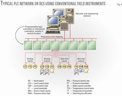
- PLC network: conventional 4-20 ma analog field instruments (transmitters and control valves) and discrete (switching) instruments, connected to several PLCs housed in an equipment room added to the control building (Fig. 4).
- Distributed control: conventional analog and discrete field instruments incorporated into a special DCS designed for small or medium plants. DCS architecture resembles that of a PLC network (Fig. 4), with "distributed" controllers taking the place of the PLCs.
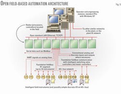
- Open field-based architecture: a totally digital network (Fig. 5) based on intelligent (microprocessor-based) transmitters and digital valve controllers (DVCs), using conventional instruments only where intelligent ones are not available or applicable. The processors or controllers to which field instruments are connected are in enclosures in the field.
Open architecture
With an open architecture, most of the newer intelligent instruments communicate on Foundation fieldbus "H1" networks, in which an ordinary twisted-pair line called a "segment" can handle signals and power for up to 16 instruments. Some intelligent instruments, however, use the earlier HART method of superimposing two-way digital traffic on a conventional analog signal.
In conjunction with appropriate modular software at other nodes (controllers and computers) in the network, these transmitters and DVCs can essentially commission themselves into the control scheme, monitor their own condition, calibrate themselves, and even execute control algorithms that were previously restricted to a central control system.
More limited communication with intelligent instruments can be provided by networks of earlier types, such as Modbus. Bus communication with simple, discrete-signal instruments can be provided by actuator-sensor-interface bus networks. Communication and operating systems are "open" in that they use industry-standard, interoperable methods such as Windows NT, Ethernet, and TCP/IP protocol rather than proprietary techniques. Thus, users are not as limited to a single vendor or its licensees as before.
Open field-based architecture outwardly resembles that of DCS and PLC networks. With conventional instruments, however, all control processing must be performed in the controllers, PLCs, or computers. Even when intelligent instruments are used in a DCS or PLC network, the older architecture hampers full use of their potential.
The third option was represented by PlantWeb from Emerson Process Management (formerly Fisher-Rosemount), applied with the DeltaV process automation system-including Emerson's asset-management software for remote instrument configuration, calibration, diagnostics, and preventive maintenance-and maximum use of Foundation fieldbus.
By April 2000, it was obvious that, although open field-based architecture was a radical departure from the preceding generation, its promises were proven. The network could readily be scaled up to automate the entire plant (including future expansions), and implementing PlantWeb in Unit No. 1 was the least expensive alternative.
Furthermore, unlike the others, this was a comprehensive package that did not require integrating a number of network components from different suppliers-except the existing pipeline RTUs, which were a simple matter.
After the construction permit was secured, work on restoring Unit No. 1 began in June 2000, with a goal to be on stream in 6 months. By September, Calcasieu decided to apply this architecture to Unit No. 2, the naphtha stabilizer, tank farm, and pipeline. Only a few auxiliary units would be left out of the network, for incorporation later.
Implementing architecture
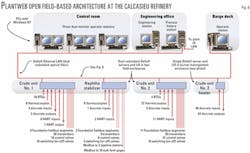
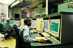
Fig. 6 shows the resulting initial implementation of open field-based automation architecture. In the control room are three operator stations in a console (Fig. 7), each consisting of a standard personal computer with Windows NT and two monitors.
In the engineering office near the control room (Fig. 6) are two more Windows NT computers-one configured as an engineering station, the other principally for maintaining the process history database. The latter PC also provides a link to the plant information systems local area network (LAN).
There is also an operator station in the small building (Fig. 2) on one of the barge docks. This station can serve as a spare operator station for the entire plant in case of a fault in the control room or section of LAN running from there to the plant. The LAN is a conventional optical-fiber Ethernet system that is entirely dual redundant, so that if there is a failure in any primary link, hub, or port, the secondary counterpart takes over.
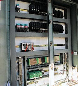
There are many different field inputs and outputs connected to each controller (Fig. 6). Two of those controllers-one for Crude Unit No. 1 and one for the naphtha stabilizer-are in the same weatherproof field enclosure (Fig. 8). The controller for Crude Unit No. 2 is in another field enclosure in that area. No addition to the control building was required and field instrument lines are optimally short.
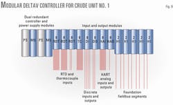
Fig. 9 illustrates the modular construction of each controller assembly, using the Unit No. 1 controller as an example. The controllers for Unit Nos. 1 and 2 and the naphtha stabilizer have dual-redundant controller modules, each with its own power-supply module and dual-redundant LAN ports.
The secondary controller continually mimics all functions of the primary, enabling automatic bumpless transfer upon detection of a fault in the primary controller or its power supply.
At the lower right in Fig. 6 is a fourth controller assembly that was built into the burner management system for the new heater in Crude Unit No. 2. That system handles safety permissives and shutdowns for eight burners fueled by natural gas or refinery offgas. The manufacturer normally programs these functions into a PLC of the user's choice, mounted in the burner management enclosure.
Calcasieu requested a DeltaV controller assembly instead because its integration into the network is more convenient than talking to a PLC via a serial data module.
Serial links, however, turned out to be the optimum method for integrating the tank farm and pipeline into the network. Those operations (Fig. 6) were connected via two 2-channel serial interface modules configured as Modbus masters, located for convenience in the controller assembly for the naphtha stabilizer. (Only one channel is used in each module.)
At the tank farm, the old manual float-gauge heads were replaced with modern intelligent units that act as Modbus slaves and also report temperature. For the pipeline, the existing Modbus line to two radios linked with distant RTUs was simply transferred from the SCADA host computer to the controller.
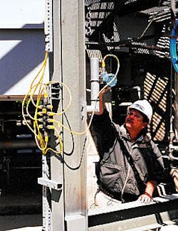
Fig. 10 illustrates fieldbus communication with intelligent instruments. Wiring for the Foundation fieldbus segments consists of standard lengths of Banner-Turck interlinkBT cabling with weather-tight quick-disconnect fittings. The cable sets and branch blocks called "bricks" are designed for Foundation fieldbus projects.
Conventional electrical conduits and purged enclosures were not required because the field instrumentation lies entirely within areas classified as Division 2 (normally safe regarding explosive atmosphere) rather than Division 1 (normally hazardous). This allows use of the exceptionally favorable protection method called nonincendive circuits.
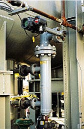
Fig. 11 illustrates another aspect of this retrofit project. At displacer-type level sensing points, the old pneumatic transmitter head and displacer were replaced by an intelligent Rosemount DLC3000 that happens to use HART rather than Foundation fieldbus. It also transmits the signal from a resistance temperature detector (RTD) in the displacer chamber, so that the level measurement can be corrected for temperature.
At temperature-sensing points critical for process control, such as heater outlets and tower overheads, existing pneumatic temperature transmitters or thermocouples were replaced by dual-redundant RTD probes connected to intelligent multivariable transmitters. Elsewhere, some existing thermocouples were directly replaced by RTDs for higher accuracy and reliability.
Return on investment
Calcasieu personnel created the plant drawings and instrument specifications in about 6 months. The Emerson Process Management representative for the area, John H. Carter Co., provided the initial systems configuration, integration, field enclosures, and operator console.
One Calcasieu technician attended a few days of schooling at Emerson. Four operators attended a 1-day review of the system and received in-house training before startup. Most of the instrument wiring was installed by Calcasieu personnel, supplemented by local trade labor. Operator displays were mostly configured by Calcasieu.
The control-room and Crude Unit No. 1 portions of the new automation-including all wiring-were installed and commissioned during 2 weeks in November 2000. Unit No. 2 and the naphtha stabilizer, in turn, were retrofitted during about 2 ? weeks, which extended into December, and included a 2-week shutdown for reworking tower trays and installing the new heater.
In December, the entire plant was started up again under PlantWeb with no problems. Operators became comfortable with the new controls in a few days. Later, the new tank-farm gauges and existing pipeline RTUs were integrated into the network by Calcasieu personnel.
The speed of installation derived mostly from the ease and convenience of running the cables to multiple instruments. The speed of commissioning, in turn, resulted from PlantWeb's making full use of the intelligence of the instruments, coupled with the universally familiar Windows environment-including intuitive drag-and-drop graphics.
Instrument commissioning and checkout involved two workers-one in the field and one at a network station in the control room-communicating by radio. As soon as an instrument was plugged into an operating fieldbus segment, it powered up and automatically began a dialog with the controller, causing an appropriate icon to appear on the commissioning display in the control room.
Calibration was accomplished in a few minutes, by remote control via the network. The instrument was then put into service simply by its icon being dragged over to the appropriate spot in the graphically represented control scheme.
Totally replacing the controls for virtually the entire refinery took less than 6 weeks with about $100,000 in outside labor. Doing it with the other alternatives would have taken at least 6 months and cost at least $350,000 more for electrical contractors alone. More importantly, Unit No. 1 was restored to service more than 4 months sooner.
The profit margin on 5,000 b/d of that bonus period went a long way towards paying the installed cost of the entire automation project, which was about $1 million.
That figure includes new control valves in Crude Unit No. 1 as well as DVCs for all existing control valves but not labor by Calcasieu's own employees.
As for continuing day-to-day payoffs at Calcasieu, the automatic self-monitoring of intelligent instruments saves on maintenance and also on process efficiency improvements that result from much higher long-term accuracy and dependability, all as compared to conventional analog instruments.
Several specific instances of performance improvements are more easily quantifiable. PlantWeb enabled a new control scheme for the naphtha stabilizer, which substantially decreased loss of valuable naphtha with the LPG byproduct. The throughput of Crude Unit No. 2 has risen by about 2,000 b/d, much of the increase attributable to improved control.
Finally, plant-wide automation enabled Unit No. 1 to be restored to service without hiring the four additional operators that would have been required with old-fashioned pneumatic instruments. It is expected that all of these ongoing savings will amount to something equivalent to an annual return of 80% on the automation investment.
Since startup of plant-wide automation in December 2000, Calcasieu has reaped further benefits from the ease with which additional instruments and process units can be incorporated into the network by plant personnel. Two more DeltaV controllers have been added as of December 2001-one for the wastewater handling area and another built into a new burner management system for the naphtha stabilizer reboiler.
Field instrument additions include six more Foundation fieldbus H1 segments (some of them with the full complement of 16 instruments) and a number of conventional inputs and outputs.
Resulting improvements in column controls in both of the crude units have allowed use of high-capacity trays and other enhancements that yield a plant capacity increase from 22,000 to 30,000 b/d.
Advanced multivariable control of the crude units will probably be implemented as a software package running in one of the network computers, providing rapid, optimum accommodation to sudden changes in crude feedstock. With some additional heater instrumentation, advanced control algorithms can save a considerable amount of fuel cost. As opportunity permits, most of the remaining minor refinery units will be brought into the network within a few years.
The authors
Jody Verret is the process and mechanical superintendent at Calcasieu's Lake Charles refinery. He joined the company in 1979 and has held positions of senior process operator and plant electrician.
Antonia C. (Toni) Bennett is the technical, safety, and environmental superintendent at Calcasieu Refining's Lake Charles plant. She joined Calcasieu in 1999 after leaving Boise Cascade Corp. where she worked in paper engineering and environmental engineering. Bennett holds BS degrees in environmental science and chemical engineering from McNeese State University, Lake Charles.
John Robert (Rob) Wood is a control systems specialist providing technical support for sales engineers and clients of John H. Carter Co., Baton Rouge, which represents Emerson Process Management in Austin, Tex. Wood has 25 years' experience in this and similar technical consultant positions at several companies in the process controls industry, including MicroMotion, Foxboro, and Hydril Control Systems Division.
Correction
An incorrect author photograph for Susan L. Starr appeared with her article "US gasoline-marketing margins statistics begin in this issue" (OGJ, Oct. 15, 2001, p. 46); here is the correct photograph.
