Tests expand knowledge of horizontal gravel packing
An extensive test program to evaluate a concentric annular packing system (CAPS) also expanded knowledge of horizontal gravel packing.
In particular, new methods are described for dealing with wellbore variations, fluid loss, bypass of problem zones such as shale streaks, friction pressure in the area open to flow above an Alpha wave, optimum Alpha-wave height, sand bridge erosion, sand concentration, velocity and sand height.
Horizontal gravel packs
Since the early 1990s, long horizontal well completions have become more viable for producing hydrocarbons, especially from reservoirs in deep water, and gravel packing with screens has become a standard method of ensuring sand control in horizontal completions.
Operators depend on a successful gravel pack in the wellbore annulus surrounding the screen to prolong the productive life of the well by controlling production of formation sand and fines.
The standard means of placing a gravel pack in a horizontal hole is with the "Alpha-Beta" gravel-pack technique.1 2 This method usually has a brine carrier fluid that contains low gravel concentrations, which are transported at relatively high flow rates through the workstring and crossover tool.
After exiting the crossover tool, the brine-gravel slurry enters the relatively large wellbore-screen annulus, and the gravel begins to settle on the bottom of the horizontal wellbore, forming a dune. Velocity across the top of the dune increases as the cross-sectional flow area is reduced because of the increasing bed height.
The velocity continues to increase as the bed height grows until the slurry reaches a minimum velocity needed to transport gravel across the top of the dune. At this point, gravel deposition stops and the bed height is said to be at equilibrium.
This equilibrium bed height will be maintained as long as slurry injection rate and slurry properties remain unchanged. Changes in surface injection rate, slurry concentration, brine density, or brine viscosity will establish a new equilibrium height.
Incoming gravel transported across the top of the equilibrium bed eventually reaches the reduced velocity region at the leading edge of the advancing dune. In this manner, the deposition process continues to form an equilibrium bed that advances as a wave front (Alpha wave) along the wellbore in the direction of the toe.
The bed ceases to grow when the Alpha wave reaches the end of the washpipe. At that instant, gravel transported along the wellbore-screen annulus begins to backfill the area above the equilibrium bed. As this process continues, a new wave front (Beta wave) returns to the heel of the wellbore-screen annulus.
During Beta wave deposition, pack dehydration mainly occurs through fluid loss to the screen-washpipe annulus.
Successful Alpha-Beta packing depends on a relatively constant wellbore diameter, flow rate, gravel concentration, fluid properties, and relatively low fluid-loss rates. Fluid loss reduces local slurry velocity and increases gravel concentration. Both effects will increase the equilibrium height of the settled bed or dune.
Fluid loss can occur to the formation and to the screen-washpipe annulus.
CAPS evaluation
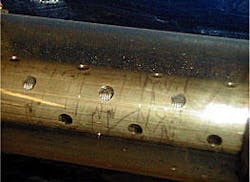
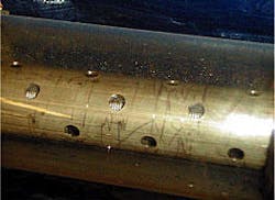
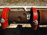
Halliburton Energy Services has been evaluating the concentric annular packing system (CAPS) concept since 1997. The CAPS assembly consists of a standard screen and washpipe that has an external perforated shroud (Fig. 1). The assembly's overall shroud dimensions and perforation diameter and distribution are designed to provide optimum packing conditions for a specific application.
The assembly increases the flexibility of the Alpha-Beta wave packing technique. It provides a secondary flow path between the wellbore and screen that allows the gravel slurry to bypass problem areas such as bridges that may have formed as the result of excessive fluid loss or hole geometry changes.3
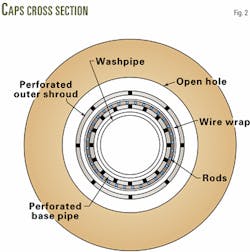
Flow is split between the three annuli. The outer two annuli (wellbore-shroud and shroud-screen) transport the gravel slurry, and the inner annulus (screen basepipe-washpipe) transports a filtered, sand-free fluid (Fig. 2).
Pressure equalizes across the three annuli because all three flow channels are in constant communication. One can assume, therefore, that the pressure in each annulus is the same at any point along the wellbore, so that the Alpha-wave heights in the outer two annuli can be determined by combining the rate-pressure calculations with a critical settling velocity correlation.
Gravel deposition in the outer annuli and fluid leakoff to the open hole or perforated interval will change the rate-pressure balance at every point along the length of the completion. Modeling of the CAPS process involves the continuous calculation of the annular rates and gravel deposition as the Alpha wave progresses to the toe of the well and as the Beta wave returns to the heel. The model reapportions the flow among the annuli remaining open in the event the openhole-shroud or shroud-screen annuli bridge off.
As soon as possible, the flow will again reapportion beyond the bridge such that the pressure equalizes in the three annuli. Flow reapportionment at the leading edge of the bridge may assist in breaking down the bridge.
The CAPS concept was validated with both small-scale physical tests and large-scale tests, including:
- 5-ft model with a 2.0-in. ID (1997).
- 25-ft model with a 6.25-in. OD and 5.25-in. ID (1998).
- 12.5-ft model with a 4.0-in. OD and a 3.75-in. ID (1998).
- 40-ft model with a 10.6-in. OD and 8.6-in. ID (1999).
- 1,000-ft model with a 6.625-in. OD and 6.065-in. ID (2000).
- 300-ft isolation model with a 6.625-in. OD and 6.065-in. ID (2000).
- 40-ft transition model with a 12.50-in. ID transitioning to an 8.6-in. ID (2000-2001).
- 85-ft friction model with a 7.0-in. OD and 6.48-in. ID (2000-2001).
The fluid flow in a wellbore with the CAPS systems can be modeled with a JAYCOR GPS2001 pseudo-3D gravel-pack model, which has been modified for CAPS, or a new model developed by Halliburton for a typical horizontal gravel-pack as well as a completion with a CAPS system.
Wellbore size
Gravel-pack completions in poorly consolidated, shaly zones can have wellbore-stability problems that can lead to other problems during the subsequent gravel-pack completion. The well can slough in or be washed out adjacent to the shale, resulting in nonuniform wellbore size. Both occurrence can prevent complete gravel placement in the annulus.
Early screenouts in North Sea, Gulf of Mexico, Asia, and South America wells have been attributed recently to ratholes. A rathole is a section at the bottom of the well without casing. For example, in the case of drilling a 121/4-in. hole and running and cementing a 95/8-in. casing string almost to the bottom of the well, the 121/4-in. openhole section below the casing seat is called the rathole.
After setting 9 5/8-in. casing, operators typically drill a 8 1/2-in. hole to TD. This creates a wellbore geometry of a 12 1/4-in. openhole section followed by an 8 1/2-in. open hole.
The gravel-laden slurry passes through the rathole as it flows from the annulus of the cased hole-screen assembly to the annulus of the open hole-screen assembly. The relatively large flow area in the rathole reduces the annular flow velocity and results in a higher Alpha wave. As the flow transitions into the smaller 8 1/2-in. openhole section, the annular velocity increases and Alpha-wave height lessens.
A pinch point can form at the junction of the 8 1/2-in. and 12 1/4-in. holes. Annular velocity tends to increase in the immediate area around this transition zone that causes a dip in Alpha-wave height as gravel moves into the normal openhole section. Alpha-wave height peaks, referred to as a hydraulic jump, then levels out to a normal Alpha-wave height for the hole size and slurry rate.
If the peak reaches the top of the open hole, a Beta wave can be triggered, causing early termination of the gravel-packing operation. A washout at any point in the openhole section could create the same scenario. Many large-scale transition geometry experiments validated this hypothesis and provided solutions to the problem.
One test model had 16 ft of 121/4-in. ID pipe followed by 24 ft of 8.6-in. ID pipe (Fig. 3). The tests run in this model included various screen assemblies, washpipe with different ODs, and a variety of carrier fluid-gravel concentrations.
The tests indicated that washouts are minimized by maintaining or obtaining a higher initial annular flow velocity through the larger diameter rathole section by doing the following:
- Increasing the initial annular flow velocity, if possible, to lower the Alpha-wave height through the potential problem area and allow the Alpha wave to propagate more or less normally.
- Running blank pipe rather than the screen across the rathole to ensure that the fluid velocity in the potential problem area is not reduced by carrier fluid loss to the screen-washpipe annulus.
- Increasing the washpipe OD to reduce fluid loss to the screen-washpipe annulus, thus maximizing the annular velocity in the rathole-screen assembly annulus.
- Lowering the gravel concentration to reduce Alpha-wave height. Gravel concentration is a parameter in the critical settling velocity calculation.
- Using the CAPS system to help maintain the Alpha-wave propagation through hole changes and areas of fluid loss at the rathole or in other areas further down the hole. The innermost CAPS annulus is a standard geometry, and the shroud provides a physical barrier to protect the flow stream within the shroud.
Fluid loss
Equilibrium bed height during the Alpha wave will increase because fluid loss reduces local slurry velocity and increases gravel concentration. Fluid loss can occur outward into the formation because of a break in the filter cake or inward into the screen-washpipe annulus.
A larger OD washpipe will control inward fluid loss. The typical washpipe OD to basepipe ID ratio should be greater than 0.80 to create sufficient back pressure to regulate the flow in the basepipe-washpipe annulus.
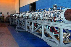
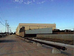
Many tests in a 40-ft long model (Fig. 4) demonstrated conclusively that the CAPS system can help bypass relatively high fluid-loss areas.4 In 2000, a 1,000-ft long model confirmed these results (Fig. 5).
Base line tests in both the 40 and 1,000-ft models led to a better understanding of the benefits of the CAPS system. Tests in the 1,000-ft model had an initial annular velocity, for instance 1.25 fps, that was reduced by fluid loss at specific points along the model. After each fluid-loss point, annular velocity decreased, and gravel concentration increased. Both changes increased Alpha-wave height.
With a slurry having an initial 1.25 fps annular velocity and a 1.65 lbm/gal gravel concentration, a 0.35 fps reduction in the slurry annular velocity immediately terminated the Alpha wave. For the same initial conditions, a 0.60 fps reduction in the slurry annular velocity allowed the Alpha wave to propagate beyond that point.
This reduction in flow rate and increase in gravel concentration, however, increased Alpha-wave height that increased system pressure over time. The pressure increase caused additional fluid loss, and an early Beta wave started one or two joints, 20-50 ft, after the fluid-loss area.
With the CAPS system, the Alpha wave could not be sustained past fluid-loss areas that reduced the annular velocity to 0.35 fps. However, tests with the fluid-loss areas that lowered the slurry annular velocity to 0.60 fps were easily bypassed, allowing a complete gravel pack.
Shale zones
Horizontal completions often contain shale zones that can be a source of fluid loss and enlarged hole diameters with subsequent potential problems during gravel packing. Shale zones also may complicate selection of the appropriate wire-wrapped screen gauge. Other potential problems of shale zones include sloughing and hole collapse after the screen placement.
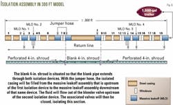
In a CAPS system with a nonperforated shroud bounded by external casing packers (ECPs), one can place a concentric bypass adjacent to the shale zone with typical CAPS annuli above and below. Tests with such a 300-ft long model indicated that one could successfully pack the areas above and below a 100-ft isolated section, as well as the concentric bypass annulus through the shale zone.
The tests simulated collapsed shale through the concentric ring formed by the nonperforated CAPS shroud and the screen. Tests included both a 25-lbm/1,000 gal HEC (hydroxyethylcellulose) carrier fluid and a brine carrier fluid.
Some tests showed massive leakoff areas upstream and downstream of the simulated shale collapse zone. Each leakoff area had a fluid-loss rate ranging from 10 to 20% of the total pump rate (Fig. 6).
The CAPS system overcame these additional complicating factors and completely packed the model.
Friction
Tests in an 85-ft long model provided friction pressure data for the unusual geometry of the area open to flow above the top of the Alpha wave. These data allowed for the development of correlations and for creating predictions for future physical and software models.
The 85-ft model consisted of a 7-in. OD steel casing with a 6.48-in. ID. The model had two acrylic viewing windows at 24.8 and 74.9 ft from the entrance with differential pressure ports, about 39 ft apart, located between the viewing windows. The tests included steel pipes of various sizes, and an Alpha wave was created by pumping a gravel slurry down the annulus formed between the model and inner steel pipe.
Differential pressure readings were obtained after one observed a stable Alpha wave in both windows. Parameters were then changed to obtain a new differential pressure reading.
The manipulated parameters included three carrier fluids (25-lbm/1,000 gal HEC, 12-lbm/1,000 gal Xanthan, and water), three gravel concentrations, annular velocities ranging from 3 to 0.33 fps, five inner pipe sizes, centralized inner pipe, uncentralized inner pipe, and partially centralized inner pipe.
Lessons learned during the friction-pressure testing program included:
- Bridge erosion. Fluids pumped through a centrifugal pump were used to rehydrate the sand pack after a bridge formed during a failed test. Further pumping at a low rate, after rehydrating of the sand pack, washed out the gravel at the outlet end of the model. Over time, a channel formed across the top of the pack, and the model was easily washed out.
This method for removing a bridge created by an early Beta wave could potentially be applied to a horizontal gravel pack in the field.
A gravel-pack test in the 40-ft transition model with a screen verified that one could remove the sand pack caused by an early Beta wave in the wellbore-screen annulus by applying a relatively low pressure to the system to rehydrate the pack and begin removing sand from the end of the model.
The test showed that one could remove a sufficient amount of sand and form a channel across the top of the sand pack, allowing sand to be washed out from the model.
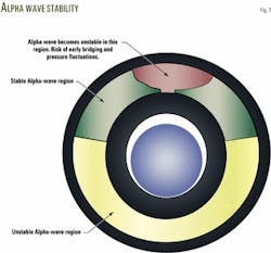
- Stable Alpha wave region. In general, the friction-loss experiments indicated that a stable Alpha wave could be formed if the Alpha-wave height was at least 50% of the wellbore height.
The Alpha-wave height would be stable as long as the top of the Alpha wave did not exceed the top of the screen (Fig. 7). A stable Alpha-wave height is defined as one that does not fluctuate or exhibit other types of chaotic motion.
- Alpha-wave height. The total friction pressure over the Alpha wave is relatively small, even though it is several orders of magnitude larger than for sand-free fluid.
Alpha-wave height increases linearly with decreasing velocity and is well behaved for both velocity and gravel concentration over the stable range. It increases as gravel concentration increases, and it grows uniformly until equilibrium height is reached. A sudden increase in pump rate forces the system to try to lower the Alpha-wave height along the entire length at once.
In these tests, large pressure fluctuations, unstable Alpha waves, and instant Beta-wave formation have resulted from sudden increases in pump rate. Continuing fluctuations in sand concentration and pump rate typically increase the instability of the Alpha-wave height with distance from the entrance.
Alpha-wave height varies little with inner pipe position. Friction pressure, however, increases significantly with pipe centralization.
References
- Dickinson, W. et al., "A Second-Generation Horizontal Drilling System," IADC/SPE Drilling Conference, Dallas, Feb. 10-12, 1986.
- Dickinson, W. et al., "Gravel Packing of Horizontal Wells," SPE Annual Technical Conference and Exhibition, Dallas, Sept. 27-30, 1987.
- Nguyen, P.D. et al., U.S. Patent No. 5,934,376, Aug. 10, 1999.
- Lafontaine, L. et al., "New Concentric Annular Packing System Limits Bridging in Horizontal Gravel Packs," SPE Annual Technical Conference and Exhibition, Houston, Oct. 3-6, 1999.
The authors
Philip Nguyen is a technical advisor in the production enhancement methods and materials group at the Halliburton Technology Center in Duncan, Okla. His current responsibilities are well completions and stimulations. Nguyen holds a PhD in chemical engineering from the University of Oklahoma.
Mike Sanders is a senior technical advisor in the production enhancement technical services group at the Halliburton Technology Center in Duncan, Okla. His current responsibilities include sand control well completions and well stimulation. Sanders holds a BS in mechanical engineering from Lamar University.
David McMechan is a senior technical advisor in the production enhancement methods and materials group at the Halliburton Technology Center in Duncan, Okla. His current responsibilities include rock mechanics and sand transport in horizontal wells. McMechan holds a BS is mechanical engineering from the University of Washington and is a registered professional engineer in Oklahoma.
Ron Gibson is principal technical professional in the production enhancement methods and materials group at the Halliburton Technology Center in Duncan, Okla. His specialties involve designing and constructing flow models and testing equipment. Gibson holds a BS in engineering technology from California Polytechnic State University, San Luis Obispo.
David Lord is a senior technical advisor in the production enhancement methods and materials group at the Halliburton Technology Center in Duncan, Okla. Recently, his efforts have been concentrated on the modeling of horizontal gravel pack operations. Lord holds a BS in chemical engineering and an MS in petroleum engineering from the University of Oklahoma. He is a member of SPE and is a registered professional engineer in Oklahoma.
