PIPELINE INSPECTION-1: Line tests confirm ILI tool for SCC detection in gas lines
In summer 1998, TransCanada PipeLines Ltd., Calgary, inspected two sections of a 914-mm (36 in.) OD gas transmission pipeline (predominantly 9.14 mm WT) using an ultrasonic liquid-coupled, crack detection in-line inspection (ILI) tool.
One objective of the inspection was to establish the condition of these pipeline sections that had a history of stress-corrosion cracking (SCC).
Also under test was the practicability of inspecting a gas line with a liquid-coupled ILI tool, specifically its ability to detect and size defects deeper than 1 mm and distinguish cracks and crack-like defects from other types of anomalies, such as inclusions and laminations.
Both sections were inspected in two independent runs, and the repeatability of inspection was assessed. Cracks and crack-like defects with depths greater than 12.5% WT from both runs were compared and correlation was established to assess repeatability.
The accuracy of tool predictions was verified in excavations in both sections: 40 reported features, varying in depths up to more than 40% were examined with respect to location, type, and size.
Examples of defect patterns, shown here, demonstrate the accuracy of the inspection method.
Detecting SCC
SCC has caused problems in pipelines all over the world and is among the defects most injurious to the integrity of the pipeline, but it is difficult to detect.
In Canada, TransCanada has reported 10 failures caused by SCC during the last 15 years. The presence and an awareness of SCC led to a National Energy Board SCC public inquiry in 1996.1
As a part of its pipeline-integrity management program, TransCanada has used various methods to investigate the condition of its pipelines and to monitor and mitigate SCC in its system.2 Most of the methods used are described in the SCC Recommended Practices prepared by the Canadian Energy Pipeline Association (CEPA) in 1997.3
Section 6 of the NEB SCC Public Inquiry Report concluded: "that it was essential [for industry] to continue [to] develop mitigative measures to deal with SCC. Most notably, the development of a fully reliable SCC in-line inspection tool would significantly improve the industry's ability to detect [and control] SCC."
Between 1986 and 1998, TransCanada fostered development of state-of-the-art ultrasonic ILI tools, which existed for inspecting natural gas pipelines and which required no liquid medium to operate.4
During this period, TransCanada inspected 600 km of pipeline with such ILI tools. One obstacle that the earlier ultrasonic tools experienced was their inability to distinguish between reflectors caused by SCC and those caused by nonmetallic inclusions, which were noninjurious.
In 1998, TransCanada decided to inspect two mainline valve sections of its system with a liquid-coupled ILI tool called the UltraScan CD. The purpose of these runs was to test the performance of the tool and encourage ILI vendors to develop internal-inspection tools specifically for gas pipelines.
Inspection scope
This 1998 CD inspection had the following objectives:
- Determine if it was possible to use the UltraScan CD tool to inspect a section of gas pipeline with limited pipeline modifications for the run.
- Assess the performance of the CD tool with regards to its capability for detecting, discriminating, and sizing of cracks and crack-like defects in a section of the TransCanada pipeline.
- Check the reliability of the CD tool by assessing its repeatability; run the tool twice in each section.
- Establish a "base line standard" for testing other inspection tools for detecting SCC and other crack-like defects.
ILI tool
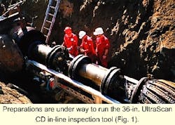
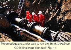
The UltraScan CD (Fig. 1) is specifically designed for detection, characterization, and sizing of axially oriented cracks and crack-like defects.5 6 It is based on 45° shear-wave technique, well established in ultrasonic nondestructive evaluation.7
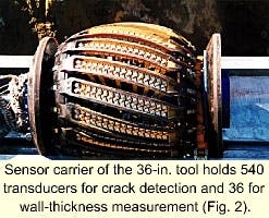
Design of the sensor carrier of the UltraScan CD tool (Fig. 2) ensures uniform scanning of the complete pipe circumference in both clockwise and counterclockwise direction with 540 sensors distributed on 18 sensor skids. This arrangement provides a multiple wall coverage ensuring that relevant reflectors are detected by up to 10 sensors.
This redundancy makes not only reliable defect discrimination but also defect sizing possible. Additionally, two sensors/skid continually measure the actual wall thickness and detect the girth welds in order to locate detected defects as precisely as possible with respect to the nearest girth weld.
The sensors are mounted on a highly flexible sensor carrier made of polyurethane (Fig. 2), fixing the sensors at a constant distance from the pipeline wall and ensuring that the correct angle of incidence is maintained during inspection.
The UltraScan CD tool can detect axially oriented cracks and crack-like defects longer than 30 mm (1.2 in.) and deeper than 1 mm. Its sizing capabilities include depth estimation, that is, classifying cracks into four depth categories:
- <12.5% WT
- 12.5 - 25% WT
- 25 - 40% WT
- >40% WT
Performing the runs
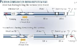
The ILI tool is based on liquid-coupled ultrasonics; therefore, the inspection had to be conducted in a slug of liquid, which in this case was chosen to be water.
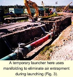
In both inspected sections, the run was performed in the so called half-batch. Temporary launchers (Fig. 3) and receivers were used in a similar way as with hydrostatic testing. While filling the section with water, the tool was run in the front of the filling column of water (Fig. 4a) behind the batching pigs.
A repeat inspection of the section was performed in the opposite direction, while the water was pumped out of the sections, this time with the tool in the rear of the water column (Fig. 4b).
Conventional hydrostatic fill pumps and dewatering air compressors were used.
All detected defects estimated to be deeper than 12.5% WT and longer than 100 mm were reported, a total of 78 crack fields (single cracks or crack colonies) deeper than 1 mm (0.04 in.) distributed in only 1.7% of joints.
Feature investigations were performed in October and December 1998, in November 1999 and in February 2000.
Verification excavations
The excavation sites were verified using the pipe tallies prepared for each CD tool run. They included odometer distances for each girth weld, joint numbers, joint lengths, measured wall thickness for each joint, and also the position of the long-seam weld for each joint. This information allowed crews to confirm that the right joint is being excavated.
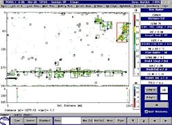
Dig sheets containing the information about the defects to be verified were complemented with C-scans of the affected parts of the pipe. Fig. 5 is an example of a compressed C-scan of an entire joint (Joint No. 12,000) with a reported SCC colony as outlined in the red boxed area of the pipe.
(A C-scan provides a two-dimensional display of the unfolded pipe wall with color-coded indications of detected reflectors.)
Investigation methods
After excavating the joint with the defect, the pipe was walnut-blasted to remove the coating and to clean the surface so the defect area could be assessed using the following steps:
- Magnetic particle inspection of the entire area to identify the damage.
- Ultrasonic testing with handheld probes measuring the wall thickness and assessing the corrosion.
- Identifying SCC, the size of colonies, the presence of interlinked cracks.
- Estimating crack depth by grinding or, in some cases, using angled UT probes.
Length measurements in the field rely on magnetic particle inspection, which is sensitive to shallower cracks than the UltraScan CD (its crack depth threshold being at about 0.5 mm). There can be differences, therefore, in determining the start and end of a colony, leading to discrepancies in measured lengths between ILI predictions and field results.
Also, in many cases, the patterns of crack fields were complex or the indications were intermittent (like the toe cracks in joint No. 827 in section MLV92-93). In both cases, the indications were not necessarily grouped together in the same way in the field as they were by the tool, causing discrepancies in measured lengths.
Measuring crack depths nondestructively in the field is very difficult, especially for crack fields, and the most reliable results are still achieved by grinding. Using ultrasonic techniques based on amplitude measurement can give only approximate values for crack depths, with an inaccuracy of up to 30% of the measured value.
Results comparison
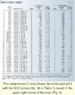
As of February 2000, 40 features had been investigated in excavations. Table 1 lists the features chosen for verification, with their location and defect type, lengths and depths, both predicted by the ILI and measured in the field.
All predicted features were found in the joints, at reported locations within the specified location accuracy (i.e., axial, ±100 mm with respect to the closest girth weld, and circumferential, ±50 mm).
The sizes (length and width) of SCC colonies were also verified to be within specifications (length: ±10% of defect length, for defects longer than 100 mm and width: ±50 mm). Some shallower or shorter SCC features were found in these inspected joints which corresponded with reflectors in the C-scans but which were not separately listed in the features listing of the CD tool inspection.
The probability of detecting all structurally significant SCC in the inspected pipeline sections was found to be 100%.
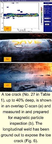
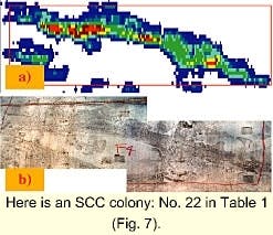
Fig. 6, showing an example of an SCC toe crack feature, illustrates the precise detection, discrimination, location, and sizing of the defect. Fig. 7 shows a comparison of a C-scan plot for a detected SCC crack field (cf) with a magnetic-particle-inspection photo image. The match of the defect pattern detected by the tool and the actual shape revealed in the digs is clear.
The investigation results of the features showed that all investigated features were correctly characterized, except for one (classified as a crack field but found to be caused by a combination of surface breaking stringers [nonmetallic inclusions] and midwall laminations).
This means if a feature was predicted to be external and either crack-like (cl) or a crack-field (cf), the field investigation showed that there was in fact an external crack feature detected during the investigative dig.
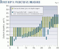
Fig. 8 shows the comparison of results for depths from ILI and the field investigations. The length of the crack fields and crack-like features were accurate in straightforward cases and oversized when the features happened to be of an intermittent nature.
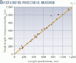
Fig. 9 shows how the length predictions compared with the field measurements.
Repeatability of inspection
The following checks were performed for both the first and the repeat inspection runs in both mainline valve sections:
All detected defects (cracks, crack fields) with an estimated depth greater than 12.5% WT from the first run were looked for in the inspection data of the corresponding reversed (second) run.
It was found that not a single defect was missed in the reversed runs.
Lengths and depth classification of defect areas obtained from both runs were compared. The results show the mean deviations in length to be ±8% and ±7% for the two inspected sections. The depths were estimated to be in the same categories for 82% of the defects in one section, and 92% of the defects in the other section.
C-scans for selected defect areas from both runs (the first and the reversed) were analyzed and defect patterns compared.
Fig. 10 shows C-scans of an SCC colony (shown also in the compressed C-scan of Fig. 5) obtained from two runs. The small box indicates the area with the deepest crack, and verification has shown that both the depth (up to 25% WT) and the length of that interlinked crack were correctly estimated. - This SCC colony shown in Fig. 5 C-scan was obtained from two independent runs in opposite directions: first run-downstream (a) and second run-upstream (b) in which the scan has to be rotated by 180° to match the downstream scan (Fig. 10).
Moreover, the shapes of the crack field are in excellent agreement even though for most parts the colony was shallower than 1 mm (0.04 in.).
In general, it can be stated that excellent agreement was obtained even for features shallower than the specified detection threshold of 1 mm.
The conclusions reached as a result of the subject program are:
- It is possible to inspect a gas pipeline using a liquid coupled In-line inspection tool such as the Ultrascan CD tool with proper preparations. The effort of carrying out the pig run preparations, however, is larger when compared to hydrostatically retesting the pipeline section.
- The Ultrascan CD tool has sufficient sensitivity and discrimination for finding and sizing SCC for integrity management purposes.
- The reliability of the tool was demonstrated by the repeat runs of the tool through the same section in opposite directions.
- A "base-line standard" has been established for measuring the performance of other ILI crack detection tools against.
References
- Public Inquiry Concerning Stress Corrosion Cracking on Canadian Oil and Gas Pipelines, Report of the Inquiry, MH-2-95, National Energy Board of Canada, November 1996.
- Delanty, B., and O'Beirne, J., "Low pH Stress Corrosion Cracking," IGU conference, June 6-9, 1992, Orlando.
- Stress Corrosion Cracking, Canadian Energy Pipeline Association, Recommended Practices, 1997.
- TransCanada Pipeline's submission to the National Energy Board's Public Inquiry Concerning Stress Corrosion Cracking (SCC) on Canadian Oil and Gas Pipelines, Proceeding MH-2-95, Feb. 16, 1996.
- Rheinland, TÜV. Verfahrensgutachten: UltraScan CD - Ultraschall-Ribetasuchmolch, 1995.
- Willems, H.H., Barbian, O.A., and Uzelac, N.I., "Internal inspection device for detection of longitudinal cracks in oil and gas pipelines," International Pipeline Conference, Calgary, June 9-14, 1996.
- Krautkrämer, J., and Krautkrämer, H., Werkstoffprüfung mit Ultraschall (Materials Testing with Ultrasound), Fifth Edition, Springer Verlag, Berlin, 1986.
The authors
Blaine Ashworth is a pipeline integrity specialist for TransCanada PipeLines Ltd., Calgary, which he joined in 1970. He holds a BASc (1970) from Queen's University, Kingston, Ont., and is a professional engineer in Alberta (APEGGA).
Neb Uzelac is a technology consultant for PII-North America, Toronto, and has also served as a technology manager in Canada for Pipetronix Ltd. after joining Pipetronix GmbH in Germany in 1993. Uzelac hold BSc, MA, and PhD in engineering science from the University of Belgrade, Yugoslavia. He is a member of NACE International and chairman of NACE Task Group 039 (formerly T10-E6 Technical Committee) "In-Line Nondestructive Inspection of Pipelines." And he is a member of the Gas Technology Institute's nondestructive examination Technical Advisory Group and of ASME International.
Based on a presentation to IPC 2000, the International Pipeline Conference, Oct. 1-5, 2000, Calgary.
