Gear-driven drawworks improve drilling efficiency
Gear-driven drawworks have gained greater acceptance in the drilling industry. They achieve improved safety, optimal performance and control, considerable weight re duction, and increased reliability over chain-driven drawworks.
In addition to several installations on land rigs, North Sea drillers have adopted the technology extensively in recent years.
Gear-driven drawworks have achieved a new performance standard, with combined drive motor regenerative braking, dynamic braking, and integration of an intelligent drawworks operational system (DOS).
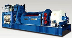
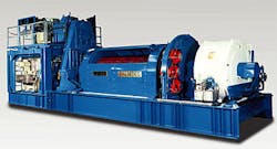
Wirth GMBH of Erkelenz, Germany has developed gear-driven drawworks with a positive-locking drive configuration, which was the prerequisite for applying all three of these attributes into one system, from both the technical and safety perspectives (Fig. 1).
The same level of performance, comfort, and safety is difficult to achieve with the traditional chain-driven designs.
Use of the four-quadrant drive mode creates additional regenerative braking power via elements and motors already in place, which is a major obstacle for a chain-drive configuration.
Four-quadrant drive
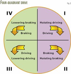
Four-quadrant drive means that energy is processed through the motors in all four drive variations of the traveling-blocks round trip (Fig. 2).
- The first quadrant represents hoisting operations. Drawworks pull the drill pipe out of the slips or spider where the maximum required energy is used for accelerating and hoisting the hook load in the lifting procedure. Gear-driven and chain-driven drawworks function essentially the same in this quadrant.
- The second quadrant represents the end of the lifting cycle. The drive motor achieves braking by acting like a generator to decelerate and stop the rising load. A mechanical brake is not needed to brake the upward momentum, as required in the drive configuration for chain-driven drawworks.
- In the third quadrant, power is applied to the motors while lowering, accelerating the load as long as the drill line is subject to tensile stress. Power applied in a controlled driven manner saves time, especially at low hook loads and when the traveling blocks are empty.
Gravity acting on empty blocks must overcome the mass inertial moments of the drawworks drum and rope sheaves in conventional drawworks.
- In the fourth-quadrant, braking while lowering, the combination of dynamic braking and regenerative braking with the drive motors is applied in the optimum range required by the control system. The mechanical brake is only used for parking or as an emergency brake.
Mechanical brake noise, of up to 130 db, is completely eliminated. This represents an active improvement in safety provisions and ensures adherence to the 85-db limit for the drill-floor area.
Since the mechanical brake serves only as a parking or emergency brake, brake maintenance is significantly reduced.
Advantages
Two side-by-side drilling operations in the Netherlands highlight the time savings derived from gear-driven drawworks, primarily from efficiencies in the third quadrant.
During a round trip to 5,000 m (16,000 ft) in two neighboring boreholes, a 2,500 hp gear-driven drawworks with two drive motors, installed on Royal Dutch/Shell Group's Prostar rig, was slightly faster than a 3,000 hp chain-driven drawworks with three motors on the Deutag Tiefbohr GMBH T-47 rig.
The physical advantage of 500 hp more lifting capacity did not make up for the efficiency of the four-quadrant gear-driven drawworks. Both drawworks had comparable pulling capacities.
With a three-speed design, gear-driven drawworks are optimally designed for operations with heavy casing loads, moderate drillstring loads, and low loads, in first, second, and third gear, respectively.
The transition from driving to braking, from quadrants 1 to 2 and from quadrants 3 to 4, place high demands on components of the drive train. Gear-driven drawworks have a definite advantage over chain drives to affect a smooth driving-to-braking transition.
Chain slack below the sprocket wheels while driving promptly changes to chain slack above the sprocket wheels upon braking. This action or sudden change in loading presents a wear and safety problem. The limits of using chain as a drive element become evident as drilling loads increase.
Manufacturers are limited in the service life they can get out of chain elements. For example, in first gear at maximum load, a chain will last only a few hundred hours. Engineers can readily design a gear drive, however, that will have extended durability and fa tigue resistance, resulting in enormous im provements in safety and maintenance.
Either AC or DC motors readily adapt to the four-quadrant drive system. AC motors, with a slightly higher braking capacity than DC motors, deliver the advantage of full load control at zero speed.
For a DC drive, however, the parking brake will take the load after a brief period, of a few seconds, to avoid blow ing the commutators. Numerous drawworks applications have used DC-motor, four-quadrant drives, which have become the state-of-the-art for gear-driven drawworks.
Optimized braking
Traditionally, a chain-driven drawworks DC motor does not perform regenerative braking. Once the DC motors have been disengaged, an auxiliary brake slows the drum to cathead speed using regenerative or dynamic braking, where the energy is dissipated as heat.
The new generation of gear-driven drawworks is equipped with two or three main DC or AC motors, which enables the operator to retard and stop a descending or ascending load smoothly and in a controlled manner.
Both the DC and AC motors in the four-quadrant mode provide regenerative braking by feeding the braking energy back into the respective 600/690-v bus or AC chopper resistor bank system.
Some engineers may state that an AC four-quadrant drive system does not require an auxiliary or dynamic brake, either electro-magnetic or hydraulic, which is true in principle. The capital expenditure of adding a dynamic brake to the system, however, will return its value with improved tripping time and added safety.
To optimize a braking system, one must consider the different performance characteristics of an auxiliary or dynamic brake and regenerative braking using the drive motors already installed.
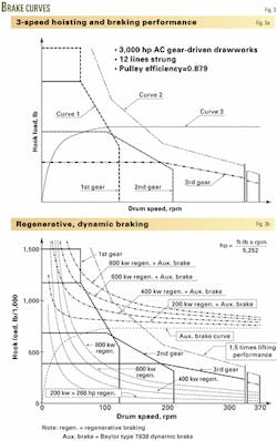
Fig. 3 shows the brake curves for a three-speed, 3,000 hp, gear-driven drawworks with two AC motors, 12 lines strung through the hoisting system, and a 0.879 pulley efficiency.
Curve 1 represents the hoisting performance of the drawworks as a function of gear, hook load, and drum speed (Fig. 3a).
Curve 2, running in parallel to Curve 1, shows the physically limited braking capacity of the AC motor drive, for each respective gear.
Curve 3 represents the braking characteristics of a dynamic or eddy-current brake. The complimentary nature of the dynamic brake, combined with regenerative braking is distinctly evident.
Regenerative braking reaches its maximum capacity with high loads and low speeds, whereas dynamic brakes perform at their maximum at high speeds, realizing braking capacities of up to 6,000 kw (Fig. 3b).
The constant power regenerative braking curves for the AC motors, when added to the braking capacity of the auxiliary or dynamic brake, yield the combined curves at the top of Fig. 3b.
The 200, 400, 600, and 800-kw regenerative braking curves depend on the minimum power usage of auxiliary rig equipment.
If an auxiliary or dynamic brake is not used, one must logically consider reduced active safety in addition to longer braking times. An accident is almost inevitable if the load-speed product goes beyond 150% of the electric motor's driving capacity.
In such a high operating range, mechanical brakes tend to fade. Water cooling of mechanical brakes does not improve their capability or safety.
Rigs perform casing operations and similar high-load work at reduced speed in the low drive ratios. The danger of dynamic overload and of exceeding the stopping capacity of drawworks is present, when tripping in the middle and lower load range without a dynamic brake.
Mechanical brakes
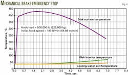
In an emergency stop without dynamic braking, tests have proven that the disk surface temperatures up to 430° C. can occur temporarily when lowering a normal string weight of about 250 tons (Fig. 4).
High temperature gradients through the thickness of the brake disk indicate that cooling water is ineffective in cool ing the brake in the short-term. The lower graphs of Fig. 4 represent the temperatures of the disk interior and of the cooling water exiting the mechanical brakes.
The disk internal temperature in creases to only about 8% of the outer brake-disk surface temperature, with a slight increase of cooling water temperature. Cooling water only contributes to mechanical brake integrity during long-term, routine operations such as tripping pipe.
Multidisk, water-cooled brakes, frequently used for drawworks, can only operate safely at loads inversely proportional to speed. To prevent thermal dam age to mechanical brakes at in creased speeds, crews must keep the maximum braking moment relatively low, which is time consuming.
Only dynamic brakes can absorb the greater energy generated at higher tripping speeds, without the potential for thermal damage or additional speed related modulation. As a result of these conditions, only the combined use of a dynamic brake and regenerative braking under normal operations, and mechanical emergency stop brake and dynamic brake in an emergency remain practical for safety reasons.
One must reach the same conclusion for economic reasons. The loss in operating speed and rig time using only regenerative braking justifies inclusion of the dynamic brake because of the almost equal equipment costs and weight of a dynamic brake compared to resistor banks.
For parking and in case of emergency, the drawworks standard disk brake is equipped with three sets of service calipers that are applied to the disk mounted on the drawworks drum.
The spring-loaded calipers require hydraulic pressure for release, providing a failsafe system. Any power loss or hydraulic failure will apply all calipers for an emergency stop.
The regular drawworks control system (DOS) will only apply the calipers for parking and under service conditions they will hold the load static, thus preventing unintentional lowering or raising of the load. The mechanical brake does not need a cooling system.
Dynamic braking
To demonstrate the benefits of using a dynamic brake in combination with regenerative braking, Shell's Prostar rig operating in Denmark performed a site test with a 2,500 hp gear-driven drawworks.
The rig performed the first test with an eddy-current brake combined with 250 kw of regenerative power. The drive motors fed power back into the source.
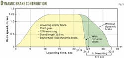
The rig performed the second test with 250 kw of regenerative power only. The results indicated an 8.5 sec loss for each stand of drill pipe run in the hole, at low block weight or essentially empty blocks (Fig. 5). A loss of 8.5 sec for every stand results in 3.8 stands/hr lost in the tripping speed.
Crews ran the test with 12 lines strung in the hoisting system, the drawworks in third gear, and at a 260 fpm (1.3 m/sec) maximum block speed.
Hoisting systems without gear-shifting ability and AC motors operating at 3,000 rpm would lose even more tripping speed. The braking capacity of AC motors at 1,600 rpm of 1.5 times driving capacity, drops to only 1.09 times the driving capacity at 3,000 rpm.
This means tripping speeds going in the hole almost equal the tripping speeds coming out, inevitably causing further serious time losses.
Eddy-current brakes perform only in dynamic conditions and can neither stop nor hold static loads. They are dir ectly attached to the drawworks shaft and act together with the motor regenerative braking in a complementary way, suitable for all dynamic conditions.
Regenerative motor braking with AC power in the four-quadrant configuration is able to brake the load to zero speed, silently, without friction, and without wear.
Moment of inertia
Disengaging the drum from the drive train of gear-driven drawworks is not allowed for safety reasons. The impact of all drive-train components on the mass moments of inertia, therefore, is important.
Besides the drawworks drum and chain drive of conventional drawworks, engineers must consider all components of the drive train in mass moment of inertia calculations, due to the locked-in engagement of the drive train in the four-quadrant drive system.
Optimal weight configuration should be of the highest priority for the latest generation of drawworks.
Compact transmission gears, with high reduction ratios, provide the minimum mass moment of inertia possible. They also provide the best solution for safety and performance in spite of their significant design challenge and high cost.
A typical 3,000-hp gear-driven drawworks with two AC motors should average 45-48 tons active operating weight, depending on noise abatement equipment required, compared to 72 tons for a comparable chain-driven drawworks.
Revenues can be gained, considering the weight, time, and cost tradeoff.
Autodriller
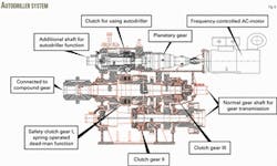
Manufacturers can build an autodriller into the system easily by adding an extra 30 or 60-kw AC drive, independent from the main drive, providing a lifting capacity of up to 350 tons at about 3.5 fpm (65 m/hr).
Drillers can control the rate of penetration with the autodriller, based on input from different parameters. Rigs can also use it as an emergency back-up for the main drive.
In case of a major failure of the drawworks AC or DC drive, drillers can pull the drillstring into cased hole at reduced speed and secure the well.
While drilling, a personal computer automatically controls the drawworks following either constant drilling speed, constant weight-on-bit, or constant mud-circulation pressure.
The autodriller can control the drilling process with high sensitivity and accuracy, maximizing the service life of drilling tools, reducing the workload on the drilling crew, and optimizing desired drilling parameters.
Theoretically, the primary AC drive could serve the same function as the autodriller, however the gearing of the main drive is not appropriate for this level of fine control (Fig. 6).
The autodriller provides redundancy in case of main drive failure. It also allows positioning of components in the mast during rig-up, before the main drives are connected.
Anticollision
In addition to the automated drawworks control system, engineers have also designed an anticollision system (ACS), which enhances safety and efficiency while moving the traveling assembly during hoisting and lowering activities.
The ACS system controls the drawworks three individual braking systems, and interlocks them with the drawworks controls and other subsystem software packages, such as Roughnecks, Pipehandler, etc., for zone management.
The anticollision system monitors the drawworks braking systems. The two programmable logic controllers (PLCs) calculate the position, speed, and braking distance required for the hook load independently.
The PLCs continuously calculate kinetic energy of the traveling load, comparing it with the total braking power actually available.
Designed into the control system's algorithm, both PLCs are able to apply the regenerative brake, eddy-current brake, and disk brake independently, taking the kinetic energy of the system and the braking capacity of the drawworks into account.
The hook position, load, and required braking distance are continuously checked and compared between both microprocessors.
Any discrepancy is regarded as an anticollision system fault and will activate the DC motor regenerative braking, eddy-current brake, and, if necessary, the disk brake, to bring the load to a safely controlled stop.
Both PLCs check the following various parameters continuously:
- Any discrepancy between the two speed and position sensors.
- Load sensor failure.
- Encoder failure.
- Position fault.
- PLC control failure.
- Power supply fault.
- Drum speed (reference signal).
- Hardware fault (i.e. PLC contacts fault).
- Hook position > 100%.
- Hook position < 0%.
"Teachpoints" for the hook position allow drillers to reproduce operational sequences, for example during trips, with high accuracy.
In automatic mode the system calculates optimum braking distance. At a position equal to twice the braking distance required, the ACS system initiates the DC motor regenerative braking and indicates to the driller that the system is active.
At the position corresponding to the full braking distance required, the ACS activates the eddy-current brake.
If the system determines that braking efficiency of the combined DC motor regenerative and eddy-current braking is impaired, it will then engage the emergency disk brake.
In conjunction with the eddy-current brake controls, the anticollision system applies DC motor regenerative braking to ensure that the maximum eddy-current brake rotor speed (drawworks drum speed) is not exceeded.
The eddy-current brake efficiency will deteriorate and safety will be compromised, if the maximum allowed rotor speed is exceeded. However, the ACS system monitors the rotor speed and prevents the drawworks from approaching this value by applying the braking system.
The amount of DC motor regenerative braking depends on the available power connected and the generating system "stiffness."
The system calculates the amount of regenerative braking that can be applied and takes this into account, which is 300 kw in the case of DC motor drive.
Drillers set the system maximum upper and lower position limits in the control room, on the ACS terminal.
The system provides analysis of the kinetic energy of the hoisting system taking into account the braking capacity of the entire system, the hook load, and speed and position of the traveling block assembly.
The author
Peter P. Heinrichs is drilling division executive vice president for WIRTH GmbH in Erkelenz, Germany. He graduated from the RWTH, Aix-la-Chapelle, branch mechanical engineering. He previously worked for Kahle/Lentjes, Düsseldorf, WIRTH GmbH., Goodwyn Offshore Foundation Work, Woodside Petroleum/ Heeremac/WIRTH Australia.
