ADVANCED CONTROLS IMPROVE OPERATION OF LUBES PLANT DEWAXING UNIT
Tim Verne
BP Oil
Kwinana, Australia
Jim Hall
Hall Controls
Bozeman, Mont.
- Stable operation of the MEK dewaxing unit
- Reduced time required by operators for solvent management
- Reduced occurrences of process upsets resulting from contamination of dry solvent
- Savings of $375,000/year, resulting in a project payback of less than 5 months.
PROCESS DESCRIPTION
The Kwinana lubes plant runs in blocked operation producing four lubricant grades: 70N (light neutral), 150N (medium neutral), 500N (heavy neutral), and SBS150 (bright stock).
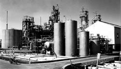
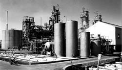
The MEK dewaxing unit is of Texaco design and was revamped in 1993 with incremental dilution and two-stage filtration technology.
Major components of the MEK dewaxing unit are the chilling, filtration, wax-free oil, and product wax sections (Fig. 1)(99789 bytes). Waxy oil is diluted with the solvent and chilled to form wax crystals. The mixture then flows to the filter feed drum, from which it is fed to the filter section.
The primary unit objective is to maintain feed rate subject to product specifications, filter section constraints, and chilling section limitations. In operation, these objectives translate to: setting the chilling outlet temperature to achieve the desired product pour point, and maximizing unit feed until the filters or chillers become limiting.
Before commissioning of the controls, operators constantly adjusted the unit throughput to keep the most limiting unit constraint at its maximum or minimum value. It was difficult for them to push and hold the process tightly to constraints because of:
- The interaction between variables
- The associated time delays
- The inherent instability resulting from periodic filter washes, exchanger depressuring, and grade changes.
Filter performance is best when the wax crystals are uniform in size. To achieve this consistency, steady operation of the chilling section at a uniform chilling rate is required.
Exchanger depressuring upsets the chilling process by heating up the chilling train to melt any wax buildup. When a chilling pass is depressured, wax crystal growth becomes nonuniform, which in turn reduces the rate at which the material can be processed by the filters.
This can result in a backup of material (a high level) in the filter feed drum. When drum levels are high, large volumes of solvent are effectively removed from the system.
To prevent serious problems, it is critical that many vessels containing solvent be maintained within limits.
For example, if the dry solvent drum is contaminated with moist solvent, significant operational problems occur. These problems are not quickly rectified and usually result in production losses, thus making constraint enforcement critical.
The process dynamics of transferring solvent within the MEK dewaxing unit include many integrating processes. (An integrating process is one such as a tank level system. When the flow rate is increased, the level will continue to increase until the flow is reduced to the original rate.)
Considerable lags and dead time exist in the recovery sections. For this reason, the task of managing and controlling the solvent inventory is time-consuming for the operator.
Unfortunately, time is at a premium for operators in the Tubes area. They are responsible for operation of the MEK dewaxing unit, vacuum unit, furfural extraction unit, bitumen blowing unit, and propane deasphalting unit.
With so much competition for attention, operators were losing the ongoing battle to effectively manage solvent inventory. Automatic control of the dewaxing unit became a high priority.
REQUIREMENTS
A control scheme was required to continuously maintain the solvent levels around the dewaxing unit. Table 1 (17159 bytes) lists the targets for the key vessels, and for the existing control schemes, which comprise single-loop level controllers.
The primary filtrate receiver contains filtered oil and solvent from the primary filters. This level needs to remain between 40 and 70%.
The existing single-loop level controller that regulated this level was able to maintain the receiver level, but was not able to judge the effect on the downstream drums containing dry and moist solvent.
The repulp filtrate receiver, which contains filtered oil and solvent from the repulp filter, generally was held in control manually. It did, however, have a high-level protection loop that set a kickback (recycle) flow from the repulp receiver to the primary receiver.
The dry solvent drum holds solvent used for filter washing. This drum is separated from the moist solvent drum by an overflow weir. This design allows excess dry solvent to overflow into the moist side.
It is important to maintain this overflow (i.e., level at 100+%) consistent with the availability of solvent because it helps keel) the moist solvent used for incremental dilutions at the proper composition. Conversely, it is necessary to maintain the moist-solvent drum level between 30 and 70% so that it does not overflow into the dry solvent drum.
Prior to implementation of the controller, contamination of dry solvent with moist solvent was common, resulting in significant production losses.
The slop solvent tank is the primary route for new solvent injection. This vessel also was controlled by a single-loop level controller, but operated without consideration for downstream effects.
Similarly, the slack wax tank level was controlled by a single-loop that manipulated the wax flow to the product wax section.
Each of these single-loop level controllers worked in isolation. A coordinated set of continuous moves in the solvent flows was required to shift solvent to deficient locations without a consequential loss of level elsewhere.
In many cases, it was not possible to find a solution that satisfied all drum level constraints. In such cases, it is necessary to be able to set priorities with regard to how those limit excursions should be allocated.
CONTROL DESIGN
The solvent inventory multivariable controller maintains key levels within limits by moving flow controllers in the MEK solvent dewaxing system. The manipulated variables for the controller are:
- Primary filtrate to waxfree oil section
- Repulp filtrate kickback
- Flow from slop tank
- Flow from slack wax tank
- Fifth incremental dilution ratio.
The controller has one disturbance variable, the total dry solvent flow. If the solvent inventory in the unit is insufficient, all level targets will be compromised according to the engineer-configured guidelines.
No limits are changeable by the operator, except those on the fifth incremental dilution ratio. (The fifth dilution is the final addition solvent in the chilling train.)
Although optimization was not a significant consideration for this application, a secondary objective was to maximize the fifth dilution and minimize the kickback solvent flow. Solvent for both these applications comes from the repulp, receiver.
The MEK dewaxing process is a unique application for multivariable control in that it consists entirely of integrating processes, as shown in the controller model matrix (Fig. 2)(66211 bytes).
Fig. 2 (66211 bytes) shows the relationships between controlled variables (CVs) and manipulated variables (MVs). Each curve in the figure illustrates the response in a given CV when an MV is increased.
Because the controller has more controlled variables than manipulated variables (i.e., more dependent than independent variables), sometimes no solution exists for the problem. This occurs because it is not possible to balance all the integrators within the limits, with the available degrees of freedom.
In these cases, the controller must be able to address the conflicting objectives with a compromise unfit a solution is possible. Honeywell's Robust Multivariable Predictive Control (RMPC) was used for this application.
RMPC is unique in its ability to handle integrating processes with more controlled variables than manipulated ones.
The software also includes a state estimation capability to predict the nature of unmeasured disturbances. This feature was required for the dewaxing unit application.
The product resides in the Honeywell distributed control system.
IMPLEMENTATION
Project implementation began with formal functional testing using a dynamic simulation of the process. In addition to the control engineers, an experienced operator and the process engineer were involved in verifying controller behavior.
Disturbance rejection is the ability of a controller to maintain targets and limits as process upsets or disturbances act on the process. Measured disturbances are process upsets that can be measured and anticipated before they cause a deviation of the control targets. Unmeasured disturbances cannot be measured because of a lack of instrumentation or knowledge.
Controller testing included the simulation of:
- Limit changes
- Measured and unmeasured disturbance rejection
- Signal failure
- Pump failure.
The controller also was tested under conditions of severe model mismatch to check overall robustness.
A safety review was carried out using a procedure that has since become a refinery standard for reviewing multivariable controller applications. This procedure includes the verification of manipulated and controlled variables and derived models, and formal approval of the controlled and manipulated variable limits and the rate-of-change limits.
Signal input criteria were also verified. These criteria include high and low limits, rate of change, and freeze checking.
A freeze check makes sure the signal does not appear frozen or stuck. For example, an instrumentation problem can cause an input to remain unchanged for, say, 15 min.
Commissioning consisted of two phases. First, the controller was run during the day shift so that its behavior could be monitored, and so that tuning parameters, including priority setting and aggressiveness, could be adjusted. Once this phase was completed, a formal 14-day test was begun.
The formal test involved 24-hr monitoring by the commissioning engineers to ensure that the controller functioned correctly over an extended time.
In the past, similar controllers had performed satisfactorily during a relatively short commissioning period, only to suffer poor utilization rates in the longer term.
The formalized approach described has become a necessary commissioning phase for all large advanced control projects at the Kwinana refinery.
PROCESS IMPROVEMENTS
Figs. 3(55777 bytes)-(59466 bytes)5(47620 bytes) detail several key operating parameters before and after commissioning of the controller. The figures include data for 6 months of operation. Three major improvements were achieved by the new controls:
- The dry solvent drum level has been held much closer to 100% since implementation of the control strategy, providing a constant overflow to the moist solvent drum.
- The moist solvent drum operates at a lower level, on average, since commissioning, thus ensuring against high levels, which can lead to contamination of the dry solvent drum.
- The repulp filtrate receiver operates at lower average inventory since the controller was commissioned, providing the additional solvent needed to keep the dry drum overflowing.
Since commissioning, the controller has been in a conflict situation almost constantly. This means that the controller usually is unable to satisfy all targets and limits, and must allocate the solvent according to tuning parameters.
These parameters, called "error weights," determine, for example, that the target for either the dry or moist solvent drum will be sacrificed if both constraints cannot be satisfied.
The high level of conflict illustrates the difficulty of the problem with which the operators have had to cope for years.
The unit operators trusted the controller immediately after commissioning. The automatic controller manages the MEK solvent system so that the operators can concentrate on production issues.
The control has provided the basis for additional advanced control work in the MEK unit. Specifically, a project is under way to improve filter control and provide a feed maximization function.


