GAS TREATMENT INSTALLED ON DUTCH NORTH SEA PLATFORM
Leo J.F.M. Festen, Joseph P.A. Bronneberg, Wilfried P.T. Brugman
Stork Protech B. Y. Schiedam
The NetherlandsDavid W. Hartmann
Amoco Netherlands Petroleum Co.
The HagueBrian L. Huber
Amoco Production Co.
New Orleans
Installation offshore of a treating system for Amoco netherlands Petroleum Co. to bring natural gas and condensate up to sales specifications runs counter to conventional development practices of putting such systems on land.
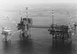
The processing scheme is for the P/15 -P/18 project in the Dutch North Sea (Fig. 1) (81740 bytes). The project is integrated with the nearby Rijn field production.
With a total estimated cost of more than I billion Dutch Guilders, the project is not only the largest single investment undertaken by Amoco and its partners but also the first in which Dutch gas has been treated offshore to sales specification.
The field produces up to 13.4 million standard cu m/day (scmd; 500 MMscfd) of gas and 1,900 cu m/day (cmd) of hydrocarbon condensate (12,000 b/d).
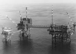
The P/15-P/18 gas development complex includes a six-pile central gas-processing platform (P / 15-D) which receives gas from three subsea wells and 4 four-pile wellhead protector platforms (WPPs) and from one WPP (P/14-A) of Wintershall Noordzee Corp. (Fig. 2) (49088 bytes).
A bridge connects P/ 15-D with the existing Rijn field oil-production platform (P/15-C) which has two WPPS: P/15-A and P/15-B (Fig. 3).
Amoco made a basic design of the gas development facilities; Stork Protech, Schiedam, The Netherlands, received in December 1990 the contract for the detailed design.
INDEPENDENT FIELDS
Amoco's existing Rijn field platform, nearby the gas fields, already provided some essential facilities: the oil export pipeline, a control room, helideck, and living quarters.
With the gas reservoirs spread over a wide area, independent field developments (that is, WPPs and ,subsea wells) were required.
The well fluids transported by the interfield pipelines to the central gas-treatment platform contain water; therefore, a hydrate inhibitor must be injected.
Methanol (CH3OH) was selected because, once it is injected at the wellheads vaporized CH3OH will also prevent hydrate formation in the complete downstream process.
The liquids in the interfield pipelines make a slug catcher downstream necessary. Even with regular sphering from the WPPS, Amoco anticipated slugs of up to 300 cu m.
The problem of handling slugs of this size on an offshore platform was solved by design of a slug catcher consisting of eight parallel vessels that fit between the main beams of the cellar deck.
Inlet separators remove the gas upstream of the slug catcher. This reduces the flow into the slug catcher so that a volume of 340 cu m is sufficient and some separation of condensate and water can be accomplished in the slug catcher.
The inlet separators and slug catcher form the inlet system (Fig. 4) (103116 bytes).
Four interconnected process units (gas dew point control, vapor recovery, condensate stabilization, and CH3OH recovery) were designed to split completely the fluids from the inlet system into pipeline quality gas, stable condensate, clean water, and CH3OH for reinjection as shown in Table 1 (20957 bytes).
Gas-dew point control, that is, control of both the water and the hydrocarbon dew point, is by cooling. The flowsheet simulation showed that most of the CH3OH condensed in the liquid phases after cooling, so that separation to recover CH3OH from the sales gas (for example, absorption in triethylene glycol) was uneconomical.
Accurate data for the three-phase equilibrium of gas-condensate-CH3OH/water were required for the design of this process. For the detailed design, the flowsheet simulation program (PRO/11 of Simsci) has been adjusted to correlate with Gas Processors Association (GPA) research data.
This resulted in accurate process simulations in the pressure range of 90 bara in the gas dew point-control unit to 9 bara in the stabilization unit.
PLATFORMS AND PIPELINES
The WPPs are simple unmanned platforms. CH3OH is injected upstream of the choke valve at each wellhead. The gas-liquids streams from all wells are combined on the WPPs and transported by interfield pipelines to P/15-D,
The sphere launchers on the WPPs can contain seven spheres that are launched by remote control from P/15-C.
Only short biweekly visits to the WPPs are planned for loading spheres and performing routine maintenance activities.
The project included 15 new pipelines as listed in Table 2 (26240 bytes). All are made of carbon steel (Grade API 5L X-52). Corrosion protection on the outside is by polyethylene (PE) coating and sacrificial anodes.
The 16 and 26-in. pipelines have concrete weight coating. The wet pipelines are internally protected by corrosion inhibitor which is mixed with the CH3OH and injected at the wellheads.
Water depth at the platforms varies between 22 and 27 m. The pipelines were installed by conventional laybarge; the CH3OH pipelines are strapped piggyback on the wet-gas pipelines.
For safety and stability, the pipelines are buried with a cover of up to 1 m. The area around the platforms is characterized by sand waves.
For burial, considerable dredging was necessary to shave the peaks of these sandwaves. The risers were pre-installed inside the jackets and later connected by spoolpieces to the pipelines.
The pipelines cross shipping lanes to the busy port of Rotterdam. Stork Protech made a quantified risk analysis to ascertain that the pipelines would meet government criteria on probability and size of spillage.
UNITS
The interfield pipelines from the WPPs are sphered regularly in order to limit the size of the liquid slugs arriving on P/15-D. Each incoming pipeline has an inlet separator (Fig. 3). These separators are sized for gas handling and have double liquid outlets to provide fast liquid dumping of incoming slugs.
Gas and liquid flow meters at these separators enable allocation of the production to shareholders of the different fields. Most of the condensate is separated from the water phase in the slug catcher.
Gas from the inlet separators flows to two identical gas dew point-control units (GDU).
In each GDU, the gas stream is cooled first in the gas-gas heat exchanger and then by expansion across a turboexpander. Condensate and water-CH3OH are separated from the gas in the cold separator at -25 C. and 79 bara. Here both the required water dew point (-8 C.) and the hydrocarbon dew point (-3 C. from 70 to 0 barg) are met.
The loss of CH3OH with the outgoing gas is only 0.04 mol % at these conditions. Equilibrium prediction revealed that there remains always sufficient CH3OH in the water phase to prevent hydrate formation.
Gas from the cold separator cools the incoming gas in the gas-gas heat exchanger and flows via a compressor (coupled to the expander) to the export pipeline.
This gas is transported ashore and flows without further treatment into the purchaser's gas-distribution grid.
During maintenance and repair the expander-compressor can be bypassed with a control valve. Then the gas is cooled by the joule/Thomson effect. This gives the same gas and condensate production but without a 4 C. margin on dew point and with 3.5 bar more pressure drop over the GDU.
The condensate flows from the slug catcher to the condensate stabilization unit (CSU). Here the vapor pressure of the condensate is reduced to less than atmospheric to meet the required specification (Rvp -11 psi) for transport ashore with the crude oil of the adjacent Rijn field platform.
The stabilizer is a distillation column with 26 trays and a reboiler using hot oil. The reflux temperature of the stabilizer is less than the boiling point of water and the reboiler temperature is greater.
Consequently, any entrained water will accumulate halfway in this column. Liquid draw-off trays have therefore been provided to remove this water phase.
The stabilized condensate from the bottom of the column contains some dissolved CH3OH which is recovered in the condensate wash column by counter-current absorption in a cleaned water stream.
VAPOR, METHANOL RECOVERY
The vapor recovery unit (VRU) consists of two 50% two-stage reciprocating compressors with coolers and knockout drums. The overhead vapor of the stabilizer column is compressed in the first stage of the VRU's compressors.
After cooling, this stream mixes with the VRU's interstage drum with the flashed liquid from the cold separator and expander suction drum and with flash gas from the stabilizer feed drum.
The cold hydrocarbon liquid from the VRU's interstage drum is returned to the top tray of the stabilizer and acts as reflux. The gas from the interstage drum is compressed by the second stage of the compressor and returned to the inlet of the GDU.
Discharge cooling for the VRU's compressors occurs by exchanging heat with the cold sales gas from the gas-gas heat exchanger. The VRU integrates the gas dew point-control unit and condensate-stabilization unit so that hydrocarbon losses are minimized.
The methanol-recovery unit (MRU) recovers the CH3OH from the water-phase of the slug catcher and also from water streams of the stabilizer feed drum, the VRU's interstage drum, and the condensate-wash column. This combined stream goes to the MRU (distillation) column.
This 24-m high packed column is designed to produce 99% pure CH3OH as overhead product and water with only 3 ppm CH3OH as bottom product. The cleansed water is sent to the adjacent Rijn field production platform for further processing or disposal.
The overhead product is cooled, and the recovered CH3OH is mixed with corrosion inhibitor, pumped in two stages to 317 bara, and flows through 2 and 3-in. pipelines back to the WPPs and subsea wells for injection in the wellheads.
As a result, no CH3OH injection pumps are required on the WPPS.
UTILITIES
The P/15-D gas-production platform has the following utilities: instrument air hot-oil system (2 x 4.5-mw furnaces), atmospheric and high-pressure vent, open and closed drain system, power generators (two 3.5-mw gas turbine-driven units), fuel gas and blanket gas, hot water (for cleaning), and a lifeboat.
The following are available on or from the Rijn C platform: control room, living quarters, helideck, potable water, firewater and service water, high pressure and low-pressure flare, diesel fuel, black start and emergency power, and rescue and lifeboats.
The main safety feature of the development is that no accommodations are present on P/15-D, and the WPPs are not normally manned.
Amoco and Stork Protech formed a separate team with TNO (Dutch Organization for Applied Scientific Research) to produce the safety case for this project.
The resultant safety case consists of a suite of 13 studies and reports covering such aspects as fire and explosion study, risk analysis, and hazardous operations.
This exercise gave valuable feedback to the design team and constitutes a useful background for developing safety procedures.
START-UP
A team of Amoco and Stork Protech started the detailed design of the P/15P/18 system in January 1991.
Amoco awarded construction of the jackets and topsides of the WPPs in February 1992 to McDermott's yard in Jebel Ali (Dubai U.A.E.). And Amoco awarded construction of the topsides of P/15-D in April 1992 to Grootint's construction yard in Zwijndrecht (The Netherlands).
The WPPs and the jacket of P/ 15-D were installed from April to June 1993. The topsides of P/15-D were placed Aug. 1, 1993, according to schedule.
First gas was delivered on Oct. 26, 1993. Start-up was formally completed Jan. 20,1994, when the full capacity of 13.4 MMscfd was reached.
