ORIENTED PERFORATING HELPS ENSURE SUCCESSFUL WELL COMPLETIONS
Hazim H. Abass
Halliburton Energy Services
Duncan, Okla.
Oriented casing perforations can help ensure successfulfracturing stimulation treatments by creating a single, wide, planar fracture in the formation, rather than nonplanar fractures such as multiple parallel fractures, reoriented fractures, and T-shaped fractures.
The perforations should be oriented in the direction that the formation is most likely to fracture when hydraulic pressure is applied.
Fracturesgenerated through oriented perforations require less pressure to initiate than out-of-phase perforations. These perforations can also control sand production from poorly consolidated formations, and in some cases, can be designed even if the in situ stress field direction is unknown.
Casing should be perforated with regard to the fracture treatment. Often, wells are perforated for the sole purpose of production. Fracture treatments are then performed later in the well's life. If wells were perforated with regard to a possible future fracture treatment, the success of the fracturing treatment and overall production gain increases.
Perforating plays a critical role in achieving a successful fracturing treatment; therefore, perforations should be designed for a given completion purpose such as well bore/reservoir communication, stimulation, or sand control.
NONPLANAR FRACTURES
As defined in Reference 1, a planar fracture is a single, wide fracture that is initiated from the well bore in the direction of the maximum horizontal stress. A nonplanar fracture is a fracture that does not follow this definition.1
Nonplanar fractures can cause excessive fluid leakoff, reduced fracture width near the well bore, elevated propagation pressure, and premature screenout.
The three basic types of nonplanar fractures are:
- Multiple fractures
- Reoriented fractures
- T-shaped fractures.
Fig. 1 (78849 bytes) illustrates these three types of nonplanar fractures and also shows a single, planar fracture.
As stated above, nonplanar fractures can cause high treating pressures and premature screenout. Reference 1 discusses tests of various rock samples to determine when nonplanar fractures occur and establishes guidelines for avoiding these fracture geometries.
Definitions of the three types of nonplanar geometries are summarized as follows:
- Multiple parallel fractures are narrow fractures created from the same perforated interval. A screenout can occur in this type of fracture system because the fractures are not wide enough at the well bore to accept large-size proppant (for example, 20/40 sand) during the fracturing treatment.
- In a reoriented fracture, a fracture is initiated along the well bore in a direction dictated by the near well bore, in situ state of stress. The fracture then reorients itself perpendicular to the minimum in situ stress as it propagates away from the well bore. Shear and tensile failure modes can result from this reorientation, causing fracture surface roughness.2
- Introducing a well bore into a formation alters the in situ state of stress and creates a new stress field near the well bore. Because of the near well bore stress field, a fracture has the tendency to initiate along the high and low sides of the well bore, while the main fracture initiates perpendicular to the minimum in situ stress forming a T-shaped fracture.
PERFORATION DESIGN
Perforations should be designed according to the fracture initiation geometry, which determines the communication path between the well bore and the fracture plane at the well bore. For a successful hydraulic fracturing treatment, perforations should be in phase with the anticipated fracture direction to ensure:1
- Propagation of a fracture that is perpendicular to the minimum horizontal stress which provides optimum width
- Creation of a single, long fracture
- Reduction of the breakdown and extension pressures.
The direction of the induced hydraulic fracture has been shown to be determined by the maximum horizontal stress of a formation rather than the perforation orientation.2 Fracturing fluid often flows through the area between the casing and formation to initiate a fracture along the maximum horizontal stress.
Fig. 2 (95615 bytes) illustrates the benefit of perforating in the fracture direction.3 When perforations are out-of-phase, near well bore communication is reduced, and the fluid must flow around the casing and in the direction of the maximum horizontal stress. Orienting perforations increases near well bore communication by allowing the fluid to flow directly into the fracture.
Three methods of perforation design can be used to create a fracture in the direction of the maximum horizontal stress. These methods are:4
- Longitudinal orientation
- Clustered orientation
- Gravity orientation
LONGITUDINAL ORIENTATION
In vertical wells that exhibit high breakdown pressure resulting from the creation of multiple fractures, perforations should be aligned in the direction of the maximum horizontal stress using a high-perforation density (12 shots/ft).4
For horizontal or deviated wells that are perpendicular to the minimum horizontal stress, align perforations along the high and low sides of the well bore. This process is also referred to as 180 phasing. Penetrate the tensile areas of the well bore to create the fracture initiation along the axis of the well. In this type of orientation, multiple completions can be performed along the horizontal section of the well bore, with each stimulated zone reaching about 10 ft.
CLUSTERED ORIENTATION
Clustered perforating can produce a transverse fracture perpendicular to the well bore. Perforating a short (1 ft) section of the interval can help reduce the occurrence of multiple fractures.
Phasing should encompass the entire 360 of the well bore circumference. If the formation is carbonate, use hydrochloric acid (HCl) in the treatment program to establish a better communication channel between the well bore and main fracture.4
GRAVITY-BASED ORIENTATION
The gravity-based orientation technique is based on the assumption that regardless of the direction and location of the deviated or horizontal well, a vertical hole oriented by gravity in the direction of the overburden stress can be created to ensure the creation of a planar hydraulic fracture. To achieve the gravity effect, weights are added to perforation shots to orient the perforation in the direction of the formation gravity.
In this application, the vertical hole deviation should be within 15 from vertical.
BREAKDOWN PRESSURE
On a study well in West Virginia, it was observed that when perforations were aligned with the fracture direction of the formation, breakdown pressure was 2,731 psi compared to 3,238 psi with perforations out-of-phase.5 This study indicated that an additional 500 psi was required to break down the misoriented perforations (Fig. 3) (28863 bytes).
An experiment using hydrostone samples to study the effects of orienting perforations in the high and low sides of the horizontal well in the direction of the anticipated fracture, showed that for perforation angles of 0, 15, and 30 the average breakdown pressure was 3,200 psi, and for angles 45, 60, and 75, the breakdown pressure averaged 4,500 psi.4
This experiment showed that fracture width is a function of perforation orientation. Fig. 4 (29728 bytes) suggests that the optimum perforation phasing is 60 or less.
SHORT INTERVALS
Perforating short intervals of a horizontal or deviated well bore can be combined with oriented perforating to reduce the occurrence of multiple fractures and increase fracturing success. This practice can be applied to all angles of a deviated or horizontal well and can be used in instances when the direction of the in situ stresses is not known or not precise.
Most fracturing treatments require only a few perforations to be successful. Short-interval or clustered perforation is a good method for deviated or horizontal wells.
Ideally, in a vertical well drilled along the maximum horizontal stress of the formation, perforations will create a single, wide, planar fracture. Often, deviated or horizontal wells are perforated in long intervals (+100 ft), which often result in multiple fractures.
In wells that cannot be drilled along the maximum horizontal stress, oriented perforating can be combined with short perforation intervals (about 1 ft) to help prevent multiple fractures and increase the chance of hydraulic fracturing success.
SAND CONTROL
Oriented perforating techniques can control sand production in a formation. A stable formation has been defined as a reservoir in which the in situ stresses are in equilibrium.4
If these formation stresses are changed, nature will compensate for the change in an effort to regain stability. These stresses can deform around the well bore, causing a stress concentration zone that can lead to sand production.
Sand is often characterized by its degree of consolidation. The term "competent sand" refers to sand that is consolidated; that is, it holds together and is tightly packed. Friable sand is sand that is poorly consolidated and cohesionless, and can be easily crumbled.
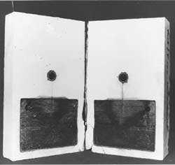
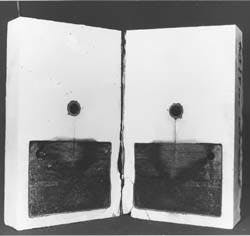
Fig. 5 shows an example of fracturing performed in friable sand. Although sand production occurs in both types of sand, different sand control methods must be employed in these formations.
In a formation containing competent sand, a breakout zone can be created near the well bore as a result of the stress concentration generated from the drilling process.4 Before performing fracturing treatments, it is important to determine whether or not a breakout failure occurred during drilling. If a breakout failure occurred, the following procedures are recommended:
- Consolidate the near well bore area before the fracture is initiated. The intrinsic, cohesive strength of the formation sand near the well bore can be increased by injecting a liquid-resinous material into the payzone.
- Perform 180 phasing in the direction of the maximum horizontal stress (Fig. 5).
- Use the maximum allowable rates (if there is no concern of breaking into barrier zones) to ensure that a planar fracture is created.
In friable sand, a plastic zone can develop around the well bore causing formation failure within that zone, leading to sand production. As the zone increases in size, sand production also increases. A circular hole should not be introduced into a poorly consolidated formation; however, the reservoir can be reached in vertical or horizontal wells through hydraulic fracturing techniques.
In vertical wells, drill the well close to, but not into, the sand formation. Perforate a 1 to 5-ft interval in the boundary layer and create a fracture using 180 phasing along the maximum horizontal stress of the formation.
In horizontal wells, drill the well close, but not into the sand formation, either in the upper or lower boundary formation. Place oriented perforations using 0 phasing on the lower or upper side of the well. Create an hydraulic fracture designed as a tip screenout treatment and use resin-coated sand through the entire job.
These methods have proven successful in poorly consolidated formations since the well bore does not penetrate the weak formation.
REFERENCES
- Abass, H.H., Hedayati, Saeed, and Meadows, D.L., "Nonplanar Fracture Propagation from a Horizontal Wellbore: Experimental Study," Paper No. SPE 24823, 67th, Washington D.C., Oct. 4-7, 1992.
- Daneshy, A.A., "A Study of Inclined Hydraulic Fractures," SPEJ, April 1973, pp. 61-68.
- Blauch, M.E., et al., "Core analysis and CT imaging improve shale completions," OGJ, Nov. 16, 1992.
- Abass, H.H., et al., "Oriented Perforations--A Rock Mechanics View," 69th SPE Annual Technical Conference and Exhibition, New Orleans, Sept. 25-28, 1994.
- Venditto, J.J., et al., "Study determines better well completion practices," OGJ, Jan. 25, 1993, pp. 91-95.
THE AUTHOR
Copyright 1995 Oil & Gas Journal. All Rights Reserved.


