Foamed cements reliably seal cased wellbores
A fully engineered, zonal-isolation process (EPP) can provide a reliable cement casing seal over the entire life of the well.
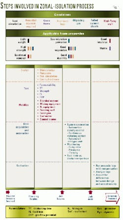
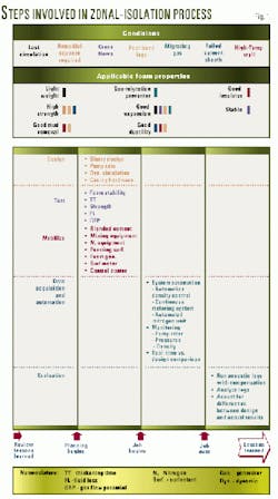
The process, which is predicated on the fully engineered application of foamed cement, was developed to meet zonal-isolation challenges presented by the following well conditions (Fig. 1):
- Lost-circulation and low-fracture gradients.
- Remedial squeezes.
- Crossflows.
- Poor bonding.
- Gas migration.
- Water flows.
- Cement-sheath failure.
- High downhole temperatures.
Background
The introduction of the oil field cementing process in the early 1900s revolutionized the oil and gas industry through the promotion of long-term production rates and the mitigation of operational problems for future workovers.
Cement serves to:
- Bond and support the casing string.
- Restrict fluid movement between formations.
- Protect the casing from corrosion and drilling shock.
- Prevent blowouts.
- Seal off lost-circulation zones.
However, even a flawless primary cement job can be damaged by stresses induced after the cement has set. Mechanical shocks such as tripping pipe and milling inside the casing weaken the bond between cement and casing.
Pressure testing during completion can also expand the casing and compresses the cement sheath, possibly damaging the bond and allowing micro-annu* to form.
Additionally, temperature and pressure cycling during production or injection can cause sheath damage due to repeated expansion and contraction of the casing. Finally, formation stresses from tectonic forces or shifting formations may cause casing collapse or separation to occur.
Foamed cement
Operational stresses and continued production from the well can cause conventional cement to break down over time and create flow paths in the annulus between the borehole and the casing. This breakdown of the cement bond can lead to pressure buildup in the annulus and can compromise the integrity of a well.
In extreme cases, this condition can even threaten employee safety and the environment. Early abandonment of the well, and consequent cessation of revenue, may be the end result of the loss of competent zonal isolation caused by a failure in the cement sheath.
Foamed cement forms a ductile and compressible medium that flexes and tolerates stresses that otherwise damage conventional cements. Inherent ductility of the foamed-cement sheath helps keep the casing and wellbore bond intact, eliminating the formation of a micro-annulus while providing greater resistance to stress cracking. These outcomes help prevent accumulation of pressure in the annulus.
Advantages include:1-6
- Higher compressive cement strengths than other lightweight slurries.
- Compressibility of the foamed cement-helps prevent gas migration and water flows.
- Variable density slurries.
- Improved mud-displacement efficiency.
- Simplified material system.
Why use an EPP?
Once an operator establishes that well conditions and operational issues dictate an applicable use for foamed cement, job execution becomes the critical issue. The simple addition of nitrogen to the cement slurry does not make an EPP, nor does it ensure achievement of all the advantages of using foamed cement over conventional slurries.
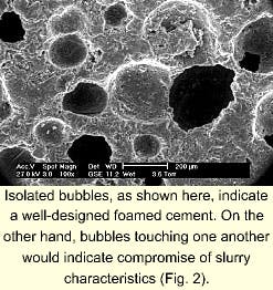
Fig. 2 shows magnified bubbles being isolated by the cement. If the bubbles touch, or if there is "breakthrough," the foamed cement characteristics become compromised. The EPP helps maintain these characteristics through proper laboratory testing of specialized slurries and the incorporation of a single-component foamer and stabilizer.
An EPP, or "premium" foam-cementing process, begins with program design assisted by personal-computer software that allows engineers to design and simulate a cement job. Software calculates the impact of complex well conditions and changes in the slurry during dynamic placement.
These calculations can be used to analyze the potential success or failure of the cementing design to achieve long-term zonal isolation; further, the designer can identify problems and design cementing parameters before cementing begins.
These functions can:
- Model the volumetric changes and increased pressure drop caused by mud erodibility.
- Predict and optimize mud displacement properties, even in eccentric annuli, by modeling the effects of changes in flow rate, rheology, or eccentricity.
- Predict and model removal of gelled mud and partially dehydrated-gelled drilling fluid.
- Predict spacer rheology required for complete mud removal, enabling cementers to properly design or "tune" the spacer systems.
- Predict frictional expansion and contraction of compressible fluids.
- Optimize centralizer spacing with any combination of holes, pipe sizes, and types of centralizers.
- At any time during the job and any well depth, predict equivalent circulating density, pump rates, pressure, density, viscosity, foam quality, nitrogen concentration, and downhole rheology.
Laboratory testing
As cements, muds, and mix-water can change from job to job and location to location. No single preflush, spacer, or cement formulation can fit all well situations. The specific material used on every job should be tested to:
- Ensure compatibility, foam stability, and optimal material selection for each job.
- Evaluate foaming muds, preflushes, and spacers ahead of the cement so as to balance fracture gradients, pore pressures, and equivalent circulating density to achieve optimum slurry placement.
- Verify pumping and mixing characteristics.
Each slurry is tailored to meet job specifications, then tested to help ensure it exhibits the desired properties. A single-component foamer and stabilizer is used as a foaming surfactant and stabilizer that can be mixed with a variety of API cements, fine-grind cement, and slag.
The foamer and stabilizer produces spherical, discrete, and uniformly sized bubbles to yield a slurry of high compressive strength-to-density ratio and superior bonding. Thickening time can range from 35 min to 6 hr.
Equipment
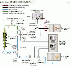
Automated foamed-cement mixing and pumping processes should include (Fig. 3):
- A cementing unit equipped with automatic density control.
- An automated, continuous metering system to inject liquid additives downstream of the mixing process.
- An automated nitrogen system that allows cementing personnel to ramp foam concentrations so as to achieve desired foamed-cement density throughout the annulus.
- A mobile control center that provides a central focal point for monitoring and controlling the cementing job.
Horizontal triplex pumps, recirculating mixers, bulk-delivery equipment, and liquid-additive pumps form the "heart" of a modern cementing system, aided by microprocessor-based automation for purposes of coordination.
Automation and data-acquisition go hand-in-hand, using the same sensors to monitor and control job parameters.
With the use of data-acquisition systems and real-time wellbore-simulation software, data from all cementing components and discrete sensors can be fed into a mobile control center, where the operation can be monitored by operators and clients. Data acquisition is used to enable last-minute job-design changes and post-job analyses that contribute to a "lessons learned" file of system improvements.
The cementing unit is based on recirculating cement-mixer technology coupled with automatic density control. This system helps ensure production of a slurry of uniform density and contributes to maintenance of a constant pump rate.
With input from wellbore simulation programs, the automatic density-control mixing equipment considers parameters such as density, yield, water requirement, and selected mixing rate. Bulk cement and water are mixed to within 0.1 ppg of specification.
The high degree of automated rate and density control allows for a smooth transition of cement mixing rate and density throughout the job, including stage changes. The automated unit proportions foaming agent and foam stabilizer to the amount of mix water on a volume-to-volume basis.
With automatic density control providing a consistent density, water volume is a known factor and can allow for accurate addition of foaming agent and foam stabilizer.
Because both foaming agents and foam stabilizers are added downstream of the cement mixer, maintaining uniform density with minimal pump-rate fluctuations ultimately improves the foam cementing process.
An automated, continuous-metering system injects foam stabilizers or surfactants into the suction header of the downhole pump after a cement slurry of uniform density has been delivered from the recirculating mixer.
Automatic features of the continuous-metering system enable it to react to changes in the pumping rate of the cementing unit to maintain a uniform concentration.
The continuous-metering system can inject chemicals at multiple points on the cementing unit. If accelerators or other liquid additives are required for the cement slurry, these liquid additives can be injected upstream of the mixer, directly into the clean mix water at the same time other chemicals are injected into the nonfoamed slurry.
The automated nitrogen unit adds the inert gas (nitrogen) at the high-pressure discharge manifold, where the cement slurry is routed from the cementing unit. One method of delivery is to maintain a constant rate within each stage. Concentration is varied by using subsequent stages, with each stage programmed for a different rate of nitrogen flow.
Nitrogen can also be added at different starting and ending setpoints so that the resulting foamed cement graph appears as a "ramp" as data are recorded. The automated nitrogen unit can enable faster response to the slightest change in pumping rate.
The mobile control center is the focal point for monitoring and controlling the cement job (Fig. 3). Data from all cementing equipment and discrete sensors can be fed into the mobile control center and connected to simulation programs loaded on personal computers, where the job can be monitored by service and operating company personnel. Mobile control centers are built in land-based and offshore configurations.
Data acquired by the mobile control center can be used to enable last-minute job-design changes and post-job analyses that contribute to a "lessons learned" file of system improvements (Fig. 1).
Use
An operator was conducting standard drilling operations offshore when a channel formed between the conductor pipe and the surface hole, threatening loss of both the well and the drilling jacket.
On this well, it became necessary to:
- Provide lateral casing support.
- Fill annular thief zones.
- Regain circulation through the conductor pipe.
- Enable density changes without redesigning the slurry.
To overcome these problems, the service company and operator placed a foamed cement around the casing to help provide support and hydraulic isolation, and help heal lost-circulation channels.
With a constant nitrogen-rate EPP operation, the service company pumped 2,000 bbl of base slurry, which was expanded by foaming to 2,650 bbl total volume. Foamed-cement returns were observed at the surface.
The operator realized almost $3 million in economic value from saving the slot in the drilling jacket, eliminating the potential for losses of unknown extent.
References
- Crook, R., Moore, S, and Miller, M., "Fully engineered foam-cementing process improves zonal isolation," Drilling Contractor, July-August 1999.
- Benge, G.O., McDermott, J.R., Langlinais, J.C., and Griffith, J.E., "Foamed cement job successful in deep HTHP offshore well," OGJ, Mar. 11, 1996.
- Deeg, W., Griffith, J., Crook, R., and Benge, G., "Foamed vs. conventional cement: cause and effect of tensile fractures in hydraulic fracturing operations," World Oil, November 1999.
- Graham, W.L., Harness, P.E., Griffith, J.E., Lee, S., Miller, J., and Maloney, B.J., "Enhanced Statistical Variation Method For Determining Zone Isolation in Complex Cements," SPE paper 28772 presented at the SPE Asia Pacific Oil and Gas Conference, Melbourne, Australia, Nov. 7-10, 1994.
- Bosma, M., Ravi, K., van Driel, W., and Schreppers, G.J., "Design Approach to Sealant Selection for the Life of the Well," SPE paper 56636 presented at the 1999 Annual Technical Conference and Exhibition, Houston, Oct. 3-6, 1999.
- Miller, L.S., and Frank, W.E., "Foam Cementing Cyclic-Steam, Producing Wells: Cymric Field Case Study," SPE paper 46215 presented at the SPE Western Regional Meeting, Bakersfield, May 10-13, 1998.
The authors
Ian Petitt is a fluids advisor for Shell UK Exploration & Production, Nova Scotia, where his responsibilities include the operational aspects of drilling fluids, cementing, and completion fluids. In his 22 years of experience with Shell Group companies, Petitt has worked as an offshore drilling engineer, contacts engineer, and production chemist. His experience includes assignments in the UK, Oman, and Canada. He holds a BS in chemistry from Edinburgh University and is a member of SPE.
Rick Covington is a technical advisor in the Zonal Isolation Technical Services Group at Halliburton's Duncan Technology Center, Duncan, Okla. Covington holds a BS in agricultural engineering from Texas Tech University and is member of SPE. He has published numerous technical papers and holds patents in cementing procedures and testing.
Mike Banse is a senior technical professional of Zonal Isolation Systems at Halliburton's Duncan Technology Center in Duncan, Okla. Banse holds a BS in agricultural engineering from Texas A&M University. He has been employed by Halliburton for 9 years, designing offshore and land-based cementing equipment.
Dave Decareaux is Halliburton's global product champion for the ZoneSeal Isolation Process. Decareaux has been with Halliburton since earning his BSEE from McNeese State University in 1980. He is a member of SPE and is a registered petroleum engineer.


