Downhole fiber-optic sensor records accoustic signals in California test
The Kern River field near Bakersfield, Calif., was the test site for a prototype downhole fiber optical acoustic sensor for investigating the continuity of oil-bearing layers.
Litton Guidance & Control Systems, Paulsson Geophyical Services Inc., and Texaco Inc. conducted the test in one of Texaco's wells in the Kern River formation steamflood, containing about nine layers of oil-bearing sandstones and averaging 700 ft in total thickness. The formation lies at a relatively shallow 1,000-ft depth.
The sandstone layers are separated by impermeable siltstones and shales with limited lateral continuity that can allow steam injected into one layer to break through to another, less-productive layer.
According to Litton, modern surface seismic techniques have been unsuccessful at Kern River because of surface statics, caused in part by a thick interval of unsaturated rock.
Field test
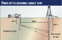
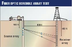
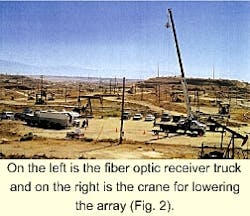
The field test recorded several cross-well data sets between two observation wells, 518 ft apart (Figs. 1 and 2).
One well, with 4-in. casing, contained the receiver, consisting of a four-channel array with a hydrophone spacing of 5 ft. The other well, with 7-in. casing, contained the source, which was a single-component axial vibrator with power source.
A workstation displayed and processed the data on-site.
Litton indicates the test showed that a clamped downhole source together with a uniform diameter array largely eliminated the common problem with tube waves.
It concluded that although Kern River formation seismic-wave attenuation and scatter are high, the source strength and receiver sensitivity provided signal bandwidth and data resolution far superior to what has been achieved with surface seismic techniques.
Fiber optics
For more than 50 years, traditional sensors developed for monitoring parameters (temperature, pressure, flow, strain, acoustics, etc.) relied on the same basic technical principle, which is a device that produced an electrical output that varied with the parameter being measured.
Through the years, improvements have primarily come in the way of improved electronic circuitry and packaging techniques (miniaturization, digitization, filtering, etc.) to more accurately translate the traditional sensor's voltage output into a usable, high-fidelity signal.
Fiber optic sensors, on the other hand, produce minute phase changes in the light traveling through an optical fiber that varies with the parameter being measured. These sensors are completely passive, contain no active electronics, and Litton expects them to be more reliable, smaller in size and weight, much simpler in operation, maintenance-free, and lower in cost.
In a fiber optic sensor system, light travels and returns from the sensor via a fiber optic cable. The sensor consists only of optical fiber coils and a device that splits the light, called an optical coupler (Mach-Zehnder hydrophone interferometer). In Litton's design no other components are required at the sensor location.
Litton says because light travels through optical fiber with very low losses, the distance from the receiver/processor to the sensor can be several hundred kilometers, with no sacrifice in performance. It adds that the fiber optic sensors operate with high fidelity in environments considered impossible for traditional sensor systems.


