New Louisiana benzene terminal, pipeline relieve traffic at chemical plant
Completion in 1999 of an integrated terminal and benzene pipeline along the Mississippi River reduced tank-truck movements to and from a chemical plant in Geismar, La., and debottlenecked supply to the plant.
In June 1999, IC OmniModal Terminal (ICOM), St. Gabriel, La., and Pipeline Technology LLC, Baton Rouge, completed construction of the terminal and pipeline.
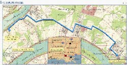
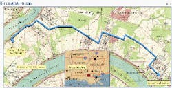
Fig. 1 shows the 10-mile route of the 6-in. pipeline from the ICOM terminal at St. Gabriel, on the eastern bank of the Mississippi River about 20 miles south of Baton Rouge to the chemical plant in Geismer.
Benzene movements
The customer's plant, which uses benzene as feedstock to produce plastic resins, needed to eliminate the constant stream of tank trucks that enter and leave the plant 24 hr/day. The company couldn't move enough trucks into the plant to keep up with current as well as future demand for its product.
It also wanted to reduce the hazards of trucks on the roads and the hazards of manually unloading benzene. Benzene is highly flammable, and its vapors are explosive when mixed with air.
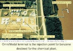
Fig. 2 shows the ICOM Terminal in a view looking to the south. Barges containing benzene arrive at the floating dock. The benzene is pumped from the river barge into the four 25,000-bbl tanks visible at the far left of the photograph.
The white strip running along the bank of the Mississippi River marks the inner face of the levee. During flood stage, the river will fill the entire channel up to the levee wall. The pipeline starts at the pump and meter station and the truck loading rack, more on which presently.
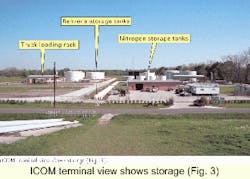
Fig. 3 shows the layout of the terminal as seen looking east from the top of the levee. The benzene storage tanks are top left. Also visible is the nitrogen storage tank. The truck rack is at left.
The barge receiving dock is a captured floating barge dock that can handle river barges. Each barge is 240 ft long and 54 ft wide containing 20,000 bbl. A barge can be unloaded in about 8 hr.
The four identical benzene storage tanks are 32 ft high, 79 ft in diameter, and hold approximately 25,000 bbl each. The tanks are of interior floating roof design. A nitrogen blanket is maintained in the space between the exterior fixed roof of the tank and the floating roof.
In case of emergency, the interior of the tank above the floating roof can be injected with foam.
The four tanks share a single concrete containment area. Benzene is miscible with water and if released on open ground can migrate into the ground water.
The containment area is covered and totally sealed with concrete. The tanks are constructed on concrete ring walls with plastic liners.
Manifold piping permits transfer from the dock into any tank and transfer between any tanks. Benzene freezes at about 45° F.
There is a recirculation system to provide for cycling the benzene through a pipe loop heated by steam tracing. Heating the benzene keeps the product fluid during cold weather.
The pipeline pump station consists of two 125-hp electric motors and centrifugal pumps. The motors are variable-speed type and the pumps are magnetic-drive type.
The magnetic drive pump was selected because it eliminates drive seals from the pump design. While magnetic-drive designs are less efficient than other types, the dominant consideration was to eliminate a potential source for a leak.
Only one pump is needed for pipeline operation. The other pump is a backup. Normal procedure is to switch pumps after each batched pipeline movement. Typical pumping rates are 300 gpm.
Both pumps discharge into a Coriolis-force mass flow meter. The advantage of the Coriolis meter in this application is that all instrumentation is external to the tube and there are no moving parts or seals to fail that contact the benzene. The meter can measure mass accurately down to plus or minus 0.13%.
The Coriolis-effect measures mass and not volume. While volume can be calculated based upon mass, it is necessary to measure temperature to account for expansion and contraction of the product.
Temperature cannot be measured as accurately as mass. In this project, an agreement was reached to convert to volume for billing purposes at an agreed upon industry standard temperature of 60° F.
Control; leak detection
An important consideration for the safe operation of the benzene pipeline is the detection of pipeline leaks. For the benzene pipeline, Pipeline Technology deployed a supervisory control and data acquisition (SCADA) system as well as a computational monitoring system (CMS).
The data communications and computer equipment for the SCADA and CMS are housed in the SCADA control building.
The most critical component of the SCADA system is the programmable logic controller (PLC), an industrial computer hardened for real-time process control applications.
The PLC continuously monitors the telemetry received from the meters and pipeline pressure and temperature sensors. This telemetry is collected locally at the ICOM terminal and from the delivery end of the pipeline over a dedicated four-wire private data line to the delivery meter at the customer's chemical plant.
All transportation and custody-transfer billing data are collected by the PLC. It also controls the pumps and is programmed upon detection of an upset condition to shutdown the pipeline automatically.
The first method to detect a pipeline leak is by means of the "What goes in, should come out" principle, or the mass-balance calculation. If less product is coming out of the pipeline than is going in, the SCADA system shuts down the pipeline.
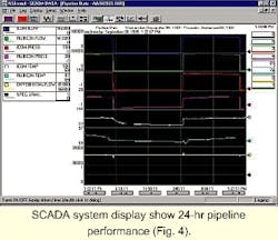
The SCADA system collects and stores all telemetry such as flow, pressure, and temperature. Fig. 4 displays the pipeline performance data for a 24-hr period.
Examination of these data tries to determine recent pipeline behavior.
In addition to the SCADA system, Pipeline Technology has deployed a computational pipeline monitoring (CPM) system.
This is the second method to detect pipeline leaks and improves the leak-detection sensitivity for smaller leaks down to 1/16 in. in diameter and improves the speed of detection of larger leaks.
In addition to flow data, the CPM monitors both real time pipeline pressure and temperature. A pipeline leak has a characteristic pressure signature. The CPM system filters the real time pressure data for this signature.
The system operates in two modes, static and steady state. In the static mode, the pipeline is shut-in. In steady state, the pipeline is at a stable constant flow.
Truck loading
The chemical process used by the customer depends upon a continuous flow of supply. If the process is shut down because of an unplanned disruption of raw materials, the cost can be high.
During a start-up and shutdown, the chemical process can produce off-specification products that must be sold at deep discount or scrapped. An unplanned shutdown can result in damage to the process equipment and production of undesired hazardous materials.
To provide a backup method of benzene delivery, a truck loading rack was deployed at the terminal. If the pipeline were to be unavailable for any reason, modes of delivery can be switched. There are two loading stations and up to 50 trucks can be loaded and dispatched in 24 hr.
The truck loading station is a bottom-loading design. The coiled cable provides for grounding of the truck chassis to eliminate a build up of static charge on the truck during loading.
Product is metered into the truck and loading stops at the meter preset. As a backup, the rack is connected to an overfill signal in the truck. At the overfill point, the supply valve will close to stop further product transfer.
As the truck is loaded with benzene, the displaced vapors are purged to a thermal oxidizer.
The vapors are mixed with propane and the mixture is incinerated at high temperature, reducing the emission of volatile organic compounds (VOCs). The hoses are of the dry-break type that eliminates spillage upon disconnection.
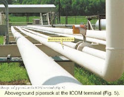
The pipeline begins at an isolation flange and travels on rack to the terminal fence where it moves underground (Fig. 5). The pipes rest on fiberglass isolation pads at each footing.
The purpose of the isolation flange and the isolation pads is to isolate the pipeline electrically from the terminal. The electric isolation is important for the effectiveness of the cathodic protection.
Protection
The benzene pipeline uses cathodic protection to protect the pipeline from corrosion. The sacrificial anode method buries a magnesium alloy near the pipeline.
Since the magnesium has a greater electrochemical potential than the steel pipeline, the natural galvanic current will flow from the magnesium anode through the soil to the steel cathode (the pipeline). In this arrangement the magnesium is sacrificed and the pipeline is protected from corrosion.
Isolating the pipeline from the terminal reduces the amount of protective current necessary and extends the life of the anodes.
The biggest threat to pipeline integrity is encroachment. The location of the pipeline is marked with signs, and an emergency-call answering bureau is maintained to receive and respond to calls on a 24-hr basis. The facility also participates in Louisiana One Call.
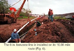
Fig. 6 shows pipe being lowered into the ditch. Even though the pipeline is cathodically protected, the primary defense against external corrosion is the factory-applied coating.
The pipe is coated in the factory and care is taken during the storage and handling in the field to prevent the coating from being damaged. Shrink sleeves are used at the welded joints to create a continuous coating.
To test the integrity of the coating, a high-voltage probe is used. The high voltage will cause a spark to jump from the probe through any holiday in the coating to the metal pipe creating a current that can be read from the scale. This test procedure is known as "jeeping." Any failures are marked and the coating is repaired before the pipe is completely lowered into the ditch.
The mainline valve is buried, leaving the valve stem, electric-motor actuator, and manual valve crank visible. Benzene has a strong capability to penetrate cracks and joints.
The underground pipeline was assembled with all welded construction. There are no flanges or threaded fittings. All underground fittings on the mainline valve were welded. The mainline valve provides a method to isolate the pipeline into two sections.
The pipeline runs along the pipe rack, crosses the road, the then proceeds on the elevated rack into the customer's chemical plant.
The authors
Sy Orlofsky is president, chief executive officer, and cofounder of Pipeline Technology LLC, Baton Rouge. He has spent 50 years in the oil, gas, electric power, and chemical business, 35 of which with Columbia Gas and its predecessor company. He was a senior vice-president with Columbia and a member of the executive committee as well as president and director of several of Columbia subsidiaries.
Orlofsky founded and was president of the Appalachian Co., an oil and gas exploration and production company, and president of Enersoft, a software services company. Orlofsky holds a BS and a professional engineering degree in mechanical engineering from the University of Missouri at Rolla.
Bruce Conti is president of IC Terminal Holding Co., St. Gabriel, La., a subsidiary of the Canadian National-Illinois Central Railroad. He has 28 years of professional experience in managing and developing terminals and transportation facilities worldwide. Previously with GATX, he held wide-ranging operations and executive positions focused on the development and expansion of the GATX' interests in Europe and Asia. Conti holds management degrees from Southern Illinois University, Carbondale, and the American Graduate School of International Management, Glendale, Ariz.
