Thread connection exceeds pipe-body plasticity
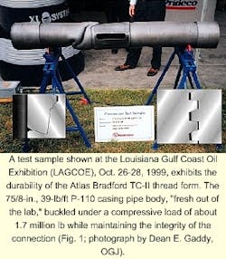
A compression test conducted on a 7 5/8-in., 39-lb/ft P-110 casing joint buckled the pipe body rather than the connection.
The test, conducted by Grant Prideco for Shell Offshore Inc.'s Brutus oil and gas field in the Gulf of Mexico, demonstrated the ability of the connection to withstand high compressive loads similar to conditions found on subsurface offshore wells.
"As an oil and gas reservoir depletes, the formation tends to collapse," says Jerry Buster, manager special accounts for Grant Prideco. This behavior in turn induces compressive strain on the pipe and connections in the 2-6% range.
"And these loads can be well above the plastic limit and even plastically deform the pipe during later production as the formation depletes and collapses."
As shown in Figs. 1 and 2, the test concluded that the connection can withstand extremely high loads while maintaining structural stability and sealability.
Test procedure
Buster says the test procedure involved placing a protective sleeve over the connection and pipe, thereby reducing the typical displacement (bulging) that occurs when compressive straining exceeds the plastic limits of the pipe.
Thus, the 8 1/2-in. ID protective sleeve helped simulate downhole conditions. Additionally, the sleeve restrains the initial bulge (initial pipe body deformation) and potentially creates several small bulges (accordion effect) that result in about a 10% strain on the pipe body.
Two samples, about 70-in. long, were tested at Stress Engineering Services Inc.'s Houston facility in a 4,000,000-lb test frame. Next, the facility applied 200 psi of internal pressure to the 75/8-in. ID pipe while increasing the compressive load until 10% strain was placed on it. This required about 1.7 million lb of force and reduced the original length from 70 in. to 63 in.
Buster says the design concept also incorporates technology that makes the connection interface transparent with the pipe body. "This allows the drilling or production engineer to use all mechanical properties of the tube without considering a reduction as a result of a threaded connection."
Thread form
The Atlas Bradford TC-II thread form employs a flank-to-flank contact where the thread body provides high resistance to axial loads from tension, compression, and bending, isolating the critical seal areas of the connection from the stress induced by well loads (Fig. 1).
The connection has the following attributes:
- It provides a tall and coarse thread form.
- The 25° stab-compression load flank stabs easy and reduces cross threading.
- The 3° tension-load flank provides improved tensile performance without the cost of a hooked-thread design.
- A tight fitting and precision tolerance thread form provides pressure sealing.
- Flank-to-flank contact eliminates galling and prevents movement from tension-compression cycling.
- It maintains equal joint strength rating in tension and compression.
- The run-out thread design optimizes tensile efficiency.
- Thread body interference distributes thread loads more evenly.
- Torque stored in thread body interference helps prevent back off.
- A seal is generated by radial interference, reducing the effects of tensile load.
- It has torque shoulder for resistance to back-off and proper makeup position.
- There is an optional Teflon seal ring.
