Successful column revamps require careful design
Reliable distillation-column revamps in refineries require careful attention to design. Seemingly subtle mistakes can have unfortunate implications.
Several refining case studies illustrate the consequences of improper process or hydraulic design, inadequate knowledge of the process unit, poor drawing reviews or procedures, and erroneous inspections. Curtailed production and unscheduled maintenance are costly, both in resources and lost opportunity.
Debottlenecking of columns for higher throughput or efficiency leaves little room for errors, since equipment is pushed to its limits.
Process design
The importance of sound process design cannot be overemphasized. Some aspects of process design that require special attention are:
- Performing a unit-test run. The unit-test run identifies equipment bottlenecks and provides direct knowledge of unit limitations and capabilities.1
- Defining revamp design objectives, alternative flow schemes, and existing equipment capabilities. This work process defines revamp objectives and saves capital cost by fully using existing equipment.2
- Running an accurate and representative process simulation. A converged simulation does not necessarily represent the process accurately. Nor does it constitute a sound design basis for the equipment review or design.
In the past, flawed distillation simulations have led to poor tower performance and unfulfilled design objectives.3
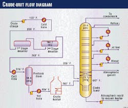
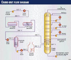
In one example, improper simulation over-predicted the distillate yield.4 Fig. 1 depicts a simplified flow diagram of the atmospheric crude unit in this case study. The unit has a preflash drum halfway in the crude preheat train.
The unit preheats the crude to 316° F. and flashes it at 36.8 psig in the drum. Flashed vapors are fed to the atmospheric-tower flash zone. The unvaporized crude goes to the crude heater. The two-phase crude leaving the heater is then fed to the atmospheric-tower flash zone.
The preflash drum effectively reduces the crude-heater duty requirement in a new unit. In revamp situations, these drums allow the refiner to increase crude-charge rates at a fixed heater duty.
One disadvantage of the flow scheme shown is that the preflash drum vapor mixes with the vapor-phase feed coming from the heater.
The preflash drum vapor is at 306° F., and the heater outlet is at 667° F. Thus, the preflash drum vapors quench the feed from the heater as they contact in the flash zone. This action downgrades some distillate into atmospheric residue.
Preflash vapors should enter the crude tower at a higher location in the column, where the quenching effect would be minimized.
The simulation of the crude tower as shown in Fig. 1 is challenging and must take into account the quenching effect in the flash zone.
Care should be taken when simulating the flashing of the drum vapor, heater vapor, and stripping-section vapor on the stage representing the bottom of the wash zone. If the simulation model artificially adjusts the stage temperature to meet an overflash-rate specification, it predicts a higher-than-actual distillate yield.
Hydraulic design
Fundamental hydraulic principles apply in the world of high-capacity trays and packing. Some of the simple yet often overlooked aspects of hydraulic design that require attention in refinery column revamps are:
- Reflux and feed entry devices.5
- Vapor and liquid product draws.6
- Reboiler draw and return arrangements.
- Sealing of downcomers against vapor bypass, especially for trays that rely on dynamic hydraulic seal.
- Hydraulic gradient on tray decks.7
The following case study details the impacts of a poorly conceived reboiler draw-and-return arrangement.
A US Gulf Coast refiner executed a revamp of a sulfur-recovery unit as part of a plant-wide turnaround. One of the project objectives was to increase the sour water-handling capability of the plant, given the anticipated sour-water increase as a result of other unit revamps.
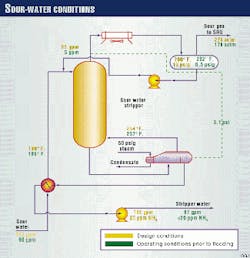
The existing trays in the sour-water stripper (SWS) lacked capacity to handle the higher sour-water make. Fig. 2 shows the design conditions for the revamp. The unit was designed to process 172 gpm of sour water. The SWS internal diameter is 4 ft, 0 in., and the stripper has 33 trays.
The revamp design conditions required that a new kettle-type reboiler along with Superfrac high-capacity trays be installed in the unit.
Following the turnaround, the SWS ran adequately while the major refinery units were brought up to full capacity. The initial sour-water rate was 85-90 gpm, and the stripped sour water met specifications (<20 ppm ammonia).
As sour water increased beyond 95 gpm, however, the tower started to flood. The pressure drop across the tower and the ammonia content of the stripped water both increased.
The operators backed off the sour-water feed rate to prevent the tower from completely filling with liquid. Fig. 2 shows the tower operating conditions just prior to the onset of flooding.
Drawings examination, field observations, and troubleshooting revealed that at sour-water rates greater than 95 gpm, the level in the bottom of the column rose above the reboiler vapor-return nozzle.
This was confirmed by two separate gamma scans by Tru-Tec Services Inc. The first scan, performed at 90 gpm, revealed trays operating normally and the bottom liquid level below the reboiler return nozzle. The second scan, done at 110 gpm, showed that the bottom liquid level was above the reboiler return nozzle and the bottom eight trays were flooded.
Cause of tower flooding
Hydraulics problems caused the tower flooding.
For a kettle-type reboiler, the driving force to move the liquid from the column into and through the reboiler and over the reboiler baffle is the liquid head in the tower bottom. Specifically, it is the liquid head between the level at the column bottom and the liquid spilling over the reboiler baffle, expressed by the following formula:8
PD = (HT 2 HK) x DL/2.31
where:
PD = Liquid head driving force, psi
HT = HeigHT of liquid in the bottom of the tower, ft
HK = HeigHT of liquid spilling over the reboiler baffle, ft
DL = Density of the liquid in the bottom of the tower, lb/cu ft
The liquid head driving force must overcome the pressure drop through the system. Such pressure drop comprises the pressure drop in the liquid pipe (including entrance loss), entrance loss in the exchanger, pressure drop through the bundle, and pressure drop in the vapor-return pipe (including entrance and exit losses).
Fig. 3 shows the nozzles, trays, and reboiler elevations for the SWS. The new reboiler was installed on an existing platform located 11 ft above the ground.
The reboiler baffle is at an elevation of 14 ft, 10 in. The reboiler vapor-return nozzle at the stripper is located at elevation 17 ft, 4 in.; it is 10 in. diameter. Therefore, the bottom of the nozzle is at elevation 16 ft, 11 in.
These dimensions leave only 24 in. of available liquid head driving force before the bottom level would reach the reboiler vapor-return nozzle. The required liquid head driving force, PD, at the design conditions, however, was 36 in.
As the operators increased sour-water feed beyond 95 gpm, the bottom liquid level reached the reboiler vapor return nozzle. Once this happened, the vapor entrained massive amounts of liquid up to the bottom tray. The bottom tray flooded, and the flooding propagated up the tower.
The engineering contractor missed the calculations of the required liquid head driving force and the tower flooded at well below its design point.
The solution to the problems consisted of replacing the two bottom trays (Nos. 33 and 32) with an internal pipe distributor. The remaining 31 trays still allowed the stripped-water specification.
The top of the pipe distributor safely discharges the vapor above the bottom liquid level and does not impinge directly against the liquid overflowing the seal pan underneath Tray No. 31.
Following a brief outage of the unit to implement these modifications, the tower processed the maximum available sour-water rate of 168 gpm.
Unit process knowledge
The selection and design of trays, packing, and internals requires knowledge of the process in which they are applied. Refining processes vary significantly with respect to the following parameters:
- Reflux and feed stream conditions (pressure, temperature, phase).
- Fouling or coking tendency of the process.
- Foaming tendency.
- Likelihood of unit upsets.
These parameters affect the mass-transfer internals selection and design. Ignoring them can lead to plugged trays and liquid distributors, coked internals, or displaced or damaged internals.
As an example, a specification for revamping a fluid catalytic cracking unit (FCCU) main fractionator called for a spray-header distributor for the slurry pumparound. The reasoning behind this design was that it is a heat-removal section.
The operating reality of FCCUs, however, is that catalyst is carried over from the reactor to the main fractionator bottoms where coke is also present.
Had a spray header been used in this revamp, circulating catalyst or coke with the pumparound stream would have eroded or plugged the spray nozzles. This section of the tower requires a trough-type liquid distributor specifically designed to resist plugging.
Equipment inspection
Inspection of mass-transfer internals by a process engineer is a much larger job than ensuring the equipment is installed in accordance with the drawings. It entails:
- Review of the equipment drawings.
- Inspection or testing of critical pieces of equipment at the manufacturer's shop, such as liquid distributors.
- Inspection of internals installation, with emphasis on details such as levelness, cleanliness, and clearances.9
Although the installation inspection is the last chance to find errors, the sooner the "inspection process" is started, the better chances of avoiding them. Successful distillation-equipment inspection requires a process engineer with knowledge of both the equipment and the process where it is being applied.
The following case study to increase the capacity of a depentanizer tower highlights the points above.
A South American refiner installed a TAME (tertiary amyl methyl ether) unit to increase production of unleaded high-octane gasoline. The unit produced oxygenates blendstock for the gasoline pool.
To prepare the C5 feed for the TAME unit, an out-of-service C4 splitter was retrofitted as a depentanizer. The depentanizer fractionates C5s from the FCCU naphtha stream. The C5 stream contains isoamylene, which reacts with methanol to form TAME.
The depentanizer is a 7 ft, 0 in. ID tower fitted with 68 trays on 21-in. tray spacing. (Trays were numbered from bottom to top.) The new service vapor and liquid traffic would result in excessively high flooding for the stripping trays. Therefore, Tray Nos. 1 through 34 were revamped with Nye high-capacity trays.
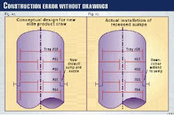
The C5 stream is a side cut from Tray No. 65. Components lighter than C5s are not fed to the TAME unit but rather taken as an overhead purge stream. This required that two new side-draw recessed sumps be installed on Tray No. 65 with corresponding draw-off nozzles, as shown in Fig. 4a.
The contracting engineering and construction (E&C) company considered the draw-off sumps simple enough to be executed directly as field modifications and did not engineer them with the high-capacity trays.
Immediately following the unit start-up, the depentanizer displayed troubling performance. A heat and material balance around the overhead condensers showed the tower was spilling liquid overhead. The sidecut composition was far from meeting specification, and the tower performance did not improve with operating moves.
The tower behaved as if the trays above the feed were flooding. The temperature profile was somewhat flat, and the total pressure drop was high.
Since the tower did not have intermediate pressure taps to isolate the troubled section, Tru-Tec Services Inc. took scans of the tower.
The scans showed that Tray Nos. 66 and higher were flooded, while Tray Nos. 1 through 65 were lightly loaded. The flooding was caused by a restriction in the downcomers of Tray No. 66. The possible causes were fouling or debris blocking the downcomers or too small downcomer clearance.
The refiner shut down the unit to inspect the depentanizer. Inspection of the top few trays made clear the cause of the liquid flooding.
As shown in Fig. 4b, someone had welded the downcomers from Tray No. 66 to the new recessed sumps installed on Tray No. 65. The internal reflux to Tray Nos. 65 and lower could only pass through the valves on Tray No. 66, competing with the rising vapors for the valves escape area. The pressure drop caused the liquid to back up to Tray No. 67 and higher.
Somewhere along the communication line between the process licensor and the E&C company, the concept of the new recessed sumps was lost and interpreted into the erroneous configuration. The E&C contractor inspected the tower prior to closure and determined everything to be in accordance to the drawings. After correcting the downcomer clearance (or lack thereof), the tower performed as expected.
Procedures review
Finally, a review of start-up, operating, and shutdown procedures is necessary to ensure a reliable column revamp. This is especially true for complex refining columns, like those with multiple side draws and heat-removal sections.
Columns that are radically reconfigured, such as the ones that are changed from a trayed configuration to packing, also require a review of procedures, along with the process-flow diagrams and piping and instrumentation diagrams.
More than likely, normal practices used prior to the revamp have to be modified for the post-revamp operation. Disregarding this aspect of a revamp can lead to unexpected start-up and shutdown problems, and even to unacceptable unsafe conditions.10
References
- Hanson, D.W., Golden, S.W., and Martin, G.R., "Make the Most of Distillation Test Runs," Chemical Engineering Progress, February 1996, pp. 72-79.
- Golden, S.W., "Minimize Capital Investment for Refinery Revamps," Hydrocarbon Processing, January 1997, pp. 103-12.
- Kister, H.Z., "Troubleshoot Distillation Simulations," Chemical Engineering Progress, June 1995, pp. 63-75.
- Hanson, D.W., and Hartman, E.L., "Process Design Pitfalls Hinder Successful Atmospheric Tower Revamp," presented at The AIChE 1997 Spring National Meeting, Paper 51-G.
- Fleming, P.B., Martin, G.R., and Hartman, E.L., "Pay Attention to Reflux/Feed Entry Design," Chemical Engineering Progress, January 1996, pp. 56-64.
- Sloley, A.W., "Drawing Distillation Products," presented at The AIChE 1997 Spring National Meeting, Paper 50-D.
- Kister, H.Z., Larson, K.F., and Madsen, P.E., "Vapor Cross-flow Channeling on Sieve Trays: Fact or Myth?" Chemical Engineering Progress, November 1992, pp. 86-93.
- Lieberman, N.P., Process Design for Reliable Operations, Gulf Publishing Co., p. 84.
- Lieberman, N.P., and Lieberman, E.T., " Inadequate Inspection cause of Flawed Vac Tower Revamp," OGJ, Dec. 14 1992, pp. 33-35.
- Hartman, E.L., and Hanson, D.W., "Startup, Shutdown and Control of Refinery Packed Fractionators," Hydrocarbon Processing, November 1995, pp. 67-73.
The Authors
Edward L. Hartman is engineering advisor on fractionation for Koch-Glitsch Inc. at Koch Petroleum's Corpus Christi, Tex., refinery. He is responsible for distillation units' process design, as well as troubleshooting, performance testing, and field installation of distillation equipment.
Hartman holds a BS in mechanical engineering from Escola de Engenharia Mau
Edlyn Menezes is a senior process engineer with Koch Petroleum, Corpus Christi, Tex. He is responsible for the crude, delayed coker, and sulfur plants. Menezes holds a BS in chemical engineering and an MBA from the University of Toronto.


