Unique HSC scenario leads to gas line failure
Tests conducted on a 24-in. section of pipe that had cracked internally revealed a unique combination of forces had led to the failure.
Failure analysis and a laboratory program confirmed that failure resulted from hydrogen stress cracking (HSC) around a dent.
Plastic deformation of the pipe occurred by a different consolidation of the soil (Marston effect), while cathodic protection generated hydrogen on the pipeline surface. When hydrogen by diffusion reached the more stressed zone after several years, cracking occurred.
At the time of 1987 failure, the pipeline transported wet nonaggressive gas, but the crack morphology resembled an environmentally assisted cracking case. Failure analysis ruled out the presence on the pipeline of hard spots or of other anomalous metallurgical zones.
A laboratory test program was developed to understand the cracking cause and to establish the hydrogen susceptibility of the steel compared with others of the same class in cathodic polarization conditions.
Constant load, constant deformation, slow strain rate, slow bending, and fracture mechanic tests were performed in substitute ocean water on a specimen cathodically polarized at -1.05 or -2 v vs. SCE.
The experimental results confirmed for all steels HSC immunity under constant-load condition, but all steels cracked from hydrogen embrittlement if they were subjected to dynamic plastic strain, while hydrogen evolution was taking place on the surfaces of the specimens.
For both smooth and notched specimens, the experimental results were similar.
A series of full-scale tests was developed to reproduce in a laboratory the cracking morphology of the field failure. A finite-element study permitted establishment of the strain condition at the tip of the indent tests similar to the strain rate chosen for the slow strain-rate tests.
Cracks with morphologies like the field failure were detected in the tests with hydrogen charge.
Cracked dent
In December 1987, a leak occurred on a 610 mm (24-in.) OD longitudinally welded pipe with a 10.31-mm WT. Design pressure was 70 bar (1,015 psi), but the normal operating pressure at the failure location was about 55 bar.
The leak was found corresponding to a cracked dent at the 6 o'clock position where the pipe rested on a rock. The bituminous asphalt coating was stripped from the damaged area.
Fig. 1 shows that the dent was shallow, only 20 mm deep (3.3% of OD), an extent that is acceptable by most specifications. Fig. 2 shows the X-ray film of the defect. A through crack with a length of 50 mm is shown together with a number of secondary cracks lying both in longitudinal and transverse directions.
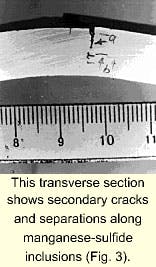
The main crack and all secondary cracks originate from the internal surface of the pipe, running in some cases perpendicularly to the surface, while others turn along planes parallel to the surface or are accompanied by separations along manganese sulfide inclusions (Fig. 3).
Such an effect is typical of a hydrogen-induced cracking (HIC) mechanism. No blister was found, however, and no separation far from the crack tip. The secondary cracks appeared opened at the crack mouth, indicating a significant strain applied during crack growth.
Examination of the fracture surfaces by a scanning electron microscope (SEM) revealed a brittle, mainly intergranular initiation with low-toughness ductile tearing crack propagation.
The pipe was produced in 1968 according to API 5L specification, Grade X-60. No uncommon characteristics were found. Tables 1 and 2 show the chemical composition and the mechanical properties of the steel.
Failure analysis suggested the possibility that hydrogen stress cracking (HSC) was the most likely failure cause. The effect of gas composition was ruled out as failure cause because no H2S and very limited CO2 and water were found.
The remaining hypothesis was that hydrogen, produced at the outside surface as a result of cathodic protection, permeated the thickness. A laboratory experimental program was developed to understand the failure causes better and to reproduce them.
Lab tests, procedure
The laboratory tests can be summarized as follows:
- Constant load (CL), constant deformation (CD), slow strain rate (SSR), slow bending (SB), and interrupted slow strain rate (ISSR) tests on un-notched samples.
- Fracture mechanics tests on single edge notch bend (SENB) samples.
CL, SSR, and ISSR tests were performed on cylindrical tensile specimens obtained according to ISO 7539-7.
For CL tests, a tensile machine provided with a double lever arm was used. A purely axial load was applied by means of two ball joints. The specimens were loaded at 100% yield strength (YS).
The SSR tests were performed on a four-station SSR testing machine that has a maximum load of 30 kN and grips displacement rate, independently adjustable for each of the four stations, varying from 510-7 to 510-3 mm/sec. All SSR tests were carried out at strain rate of 10-6 sec-1.
In the ISSR tests, the displacement of the grips was stopped when the load acting on the specimen reached a value equal to 100% of the maximum load obtained during the SSR tests performed under the same polarization conditions. The specimen was held under fixed-grip conditions for 10 days if no fracture occurred.
Constant deformation specimens were machined according to ASTM G30-90 Type B Standard Practice. The U-bend specimens were assembled on a stainless steel plate and electrically insulated by use of PTFE gaskets placed in a polypropylene vessel filled with the test solution and stirred by an immersed pump.
SB tests were performed on three-point bending specimens according to ASTM E 290-81; the clevis displacement was chosen to obtain a specimen strain rate of 10-6 sec-1.
SENB tests performed in air were carried out according to ASTM E 813-87 and E 1152-87 standards and ESIS P1-92 recommendations for determining the fracture resistance of ductile materials (J-R curve).
Crack extension was measured by use of the potential drop technique. J-R tests in substitute ocean water were carried out by use of the multispecimen method.
All tests were carried out in substitute ocean water (ASTM D 1141-90); a 1-l. solution vessel was used. A circulating flow loop with 25 l. volume served as a reservoir. The experimental procedure has been described elsewhere.1 2
Cathodic protection was imposed with a potentiostat. The level of cathodic polarization ranged from -0.9 v to -2 v vs. SCE. For comparison, SSR, SENB, and full-scale tests were also performed in air.
Results
Table 3 reports the results of CL, CD, and ISSR tests; no failure occurred in these tests.
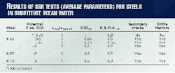
Table 4 shows the ratios between the parameters obtained by SSR tests (maximum load, Ys; total elongation, El; and percentage of reduction in area, R.A.) in aggressive environments and in air. Values for hydrogen effects were less than 1.
It can be seen that the last two ratios decrease when cathodic polarization is increased. The presence of secondary cracks and of brittle areas on fracture surface confirms the HSC effect. No differences were observed between the pipeline steels tested.
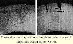
The results of SB tests were quite similar to those obtained in SSR tests. Fig. 4 shows an SB specimen after the tests in NaCl 3.5% solution at E = -1.05 and -2 v vs. SCE: The presence of cracks, with a brittle and broached propagation, can be noted on the specimen's maximum stressed area.
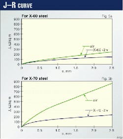
Fig. 5 shows the mechanical fracture test curves obtained in air and in substitute ocean water. When cathodic polarization is appied, the slope changes with respect to air for all the materials.
The influence of hydrogen embrittlement is confirmed by JIC and dJ/da values computed in the two test conditions (Table 5). Steel X-60 shows the least resistance to stable crack extension both in air and in substitute ocean water.
The differences are not so remarkable as to suggest that this steel is more susceptible to hydrogen embrittlement than others. The fracture surfaces are similar for all materials cathodically polarized.
SEM examinations show brittle areas on all specimens polarized at -2 v vs. SCE.
Continuous deformation
In agreement with data found in the literature,3 the laboratory tests confirmed that, for this class of steels in presence of a cathodic polarization, HSC can only occur when the applied stress increases at a very slow rate until a high level of plastic deformation is reached.
A slow and continuous deformation is indispensable to have HSC effects as demonstrated by the ISSR tests: In fact, when the plastic strain was stopped, no crack nucleation or propagation appeared.
The HSC crack nucleation begins only when the specimen is highly plastically strained.
The fracture mechanic tests confirm, however, that, also in presence of hydrogen, this class of steels maintains reasonable toughness so that the ductile fracture propagation energy for the polarized specimens is lower than ones in air, but not zero.
On the other hand, also fully saturated by hydrogen, these steels present a mixed ductile and brittle fracture: brittle in the zone of the crack nucleation and totally ductile in the core of the specimen, in which the fracture takes place when the crack size has reached a critical value.
No large zones of mixed brittle and ductile fracture were evident. This could be explained by the fact that hydrogen-assisted propagation takes place more slowly than the ductile fracture, about equal to the specimen strain rate.
HSC phenomena occur independent of the loading mode or the pipeline steel but are strictly correlated with the applied potential and the strain rate. Cathodic protection maintained the pipe at a potential sufficiently negative to generate hydrogen. Under constant load conditions, however, in absence of a continuous plastic deformation, it is insufficient to lead to HSC.
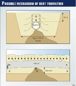
Therefore, a finite-element analysis was carried out to establish the stress state that could generate the plastic deformation.4 Here is a possible mechanism:
The pipe was accidentally laid on a rock that cannot be plastically strained by the pipe weight. About 13 kN/m acted on the pipe; this stress corresponds to the weight of the pipe itself and of 1 m backfill.
Successive hydraulic tests increased this load to 16 kN/m, giving rise to first dent formation. The hydraulic test period was, however, insufficient to allow enough hydrogen to permeate and generate the cracks. Furthermore, in many cases, the cathodic-protection system was not working at that time.
During the process of compacting, which can take 1 or 2 years after pipe laying, the actual soil load increased as a result of the consolidation of the loosely packed backfill on either side of pipeline reaching a final value estimate at 20 kN/m. This is known as the "Marston effect."5
The load to start plastic deformation on the pipe under consideration can be estimated at about 100 kN. A 20-30 mm deep dent requires a load of 200-250 kN. As a consequence, a 10-m pipe length behaving as a one-point supported beam, corresponding to a height of the rock of 28 mm (Fig. 6), suffices to explain the dent found.
The 2-year period in which the load was slowly increasing while the cathodic-protection system was generating hydrogen was consistent with the findings of laboratory tests.
Demonstration
To demonstrate this hypothesis, full-scale tests were carried out on pieces of the failed pipeline. An epoxy paint was used to obtain a localized effect of hydrogen in the most stressed area of the specimen.
The specimen was placed in a Plexiglas vessel on the table plate of a universal testing machine (Fig. 7). The movable crosshead speeds were 0.1 and 0.01 mm/min. A finite-element analysis calculated a corresponding strain rate of 10-5 sec-1 and 10-6 sec-1. A ball indenter strained the section of the pipe at a predetermined compression-load deflection.
Two levels of polarization were chosen: -1.05 v and -2 v vs. SCE.
Like SSR and slow-bending tests, the HSC susceptibility was evaluated by the comparison between the load vs. indenter displacement curves in the different conditions. No real differences were observed.
Examination of the dent showed that a strained area of about 40 mm diameter was present with the same morphology for all the specimens.
Visual examination of the inner and outer surfaces of the specimens tested in air showed no cracks. Magnetic powders, ultrasonic control, and X-rays also confirmed the absence of cracks.
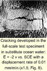
Meanwhile, the presence of several cracks was detected on the samples tested in the environment when hydrogen was being generated.
The cracks lay along longitudinal directions and were branched (Fig. 8). Table 6 reports the size of the cracks after all the tests. It is possible to observe that the crack extension is related to both the cathodic polarization and the strain rate.
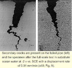
Fig. 9 reports the metallographic sections of a crack detected on the failed pipeline and on a laboratory specimen. The cracks are very similar: transgranular, with a preferential growth along the longitudinal manganese sulfur inclusions. SEM analysis evinced the presence of brittle areas on the fracture surface with the same morphology of the field defect.
These results prove the HSC effect on the field failure.
References
- Bolzoni, F., Cabrini, M., Caccia, M., and Tarenzi, M., "Hydrogen Embrittlement of Pipelines Steels Under Cathodic Protection: Comparison of Various Test Methods" in Progress in the Understanding and Prevention of Corrosion, J.M. Costa and A.D. Mercer, Eds., the Institute of Materials; Vol. 2, pp. 1500-08; Cambridge University Press, 1993.
- Pistone, V., Tarenzi, M., and Cabrini, M., "Hydrogen Stress Cracking in a Dent. Case History and Laboratory tests," Proceedings of EPRG/PRC, 10th biennial joint technical meeting on line pipe research, Apr. 18-21, 1995, Paper Number 31, pp. 31/1-31/16.
- Herbsleb, G., and Schwenk, W., Corrosion 41 (1985), p. 431.
- Bolzoni, G., Deformazioni plastiche su condotte interrate indotte nel tempo da assetamenti del terreno (Internal report SNAM 2/95).
- "Requirements for steel pipeline transportation systems," Nederland Standard NEN 3650.
The Authors
Valentino Pistone is manager of research and development in transportation technology in the technical department of Snam, the Italian natural gas transmission company. He joined Snam in 1982 and holds a degree in mechanical engineering from the Politecnico of Milano.
Marco Tarenzi is currently involved in the management of Snam's foreign pipeline systems in Europe and Tunisia. He graduated in mechanical engineering at the Politecnico de Milano in 1988 and joined Snam's research and development department in 1990.
Ennio Singaglia since 1999 has been responsible for the safety, environmental, and health department in Greek gas lines management. He graduated in chemical engineering at the Politecnico de Milano in 1990. In 1991, he started working on corrosion problems in the metallurgical laboratory of Snam. In 1998, he was responsible for the stress corrosion cracking aspects of the Snam project "New Materials for Long Distance High Pressure Pipelines."
Marina Cabrini is professor of science and technology of materials in the mechanical engineering department of the University of Bergamo where she has been a researcher since 1997. She graduated in industrial chemistry (electrochemical metallurgical) at the University of Milano in 1989. She worked from 1991 to 1997 at the Polytechnic of Milan, applied physical chemistry department.
