Harbor pipelay is one of the world's longest bottom-pull jobs
SINGAPORE ACTIVITY
One of the world's largest bottom-pull installations, a 4.5-km pipeline bundle for Shell Eastern Petroleum, was completed in May in the busy Singapore harbor.
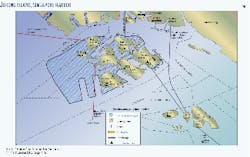
The bundle consists of eight pipelines and two fiberoptic cables connecting Shell's refinery on Pulau Bukom Island with the Petrochemical Corp. of Singapore on Jurong Island (Fig. 1). The bundle was been installed by Kvaerner E&C Singapore under the Sinki Fairway.
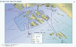
The lines, part of a $100-million expansion of Shell's oil refinery complex, will carry naphtha and other products, linking Shell's new condensate splitter unit on Pulau Bukom with Petrochemical Corp. (Fig. 2). Water depth at some points reaches 28 m.
The 8 pipelines and two fiber-optic cables, giving a combined pipeline length of more than 36 km. The previous biggest job in Singapore involved a bundle of 15 pipelines and three cables with a combined total length of 16.5 km; Kvaerner also designed it.
Bottom pull
Kvaerner E&C Singapore (formerly Kvaerner R J Brown) has been active in Singapore for more than 30 years and, in that time, has been involved in more than 95% of the country's submarine pipeline projects. Many of these have been put in place using a technique known as 'bottom pull.'
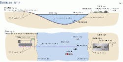
Bottom pull effectively means pulling a pipeline (or a bundle of pipelines) from one shore across a seabed to another shore. It is particularly suited to exceptionally active marine areas like the Port of Singapore where conventional techniques, such as lay barge and surface tow, would cause too much disruption to one of the world's busiest shipping lanes.
Fig. 3 presents both a profile (Fig. 3a) and a plan view (Fig. 3b) of a typical bottom-pull configuration.
For multiple pipelines, such as Shell's bundle, bottom pull is the ideal installation method as a pipelay operation would require too wide a trench.
Busy sea lanes; changing seabed
Selecting the appropriate pipeline route in this busy shipping area presented the first of several challenges.
Singapore has an extensive network of submarine pipelines and cables that must be left undisturbed. Full approval from local authorities was required for all the options as the future plans for this already congested submarine real estate had to be carefully considered.
The seabed profile, the sub-bottom profile, and seabed soil conditions were critical in the selection of a suitable pipeline route. Avoiding rock would keep the cost down and shorten the schedule.
Another stringent constraint was the minimum draft requirement of 18.5 m from the highest point of the heavy protective rock layer to the low water to allow for current and future shipping movements.
Environmental impact and risk-assessment studies ensured that the pipelines posed the minimum environmental impact and minimum risk to surrounding facilities, shipping lanes, and reefs during construction and throughout the pipeline bundle's life.
Rock layer
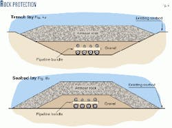
Singapore legislation demands that the bundle be protected by a layer of armor rock to prevent damage from anchors and other dropped or dragged objects.
An Australian research institution conducted model tests to check the design basis of the rock-armor protection layer.
Utilizing scale-model tests, researchers tested various anchor sizes to ensure that rock armor would perform under a variety of different conditions: anchors being dropped directly onto the rock armor, for example, and being dragged across the rock armor-protected bundle.
Fig. 4 presents the configuration for this protection: Fig. 4a shows the pipeline bundle trenched and covered with the protective rock armor; Fig. 4b shows the bundle lying on the seabed and covered with protection.
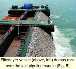
The filter layer rock and the armor protection rock must be prepared to certain tolerances to provide maximum protection and not damage the pipeline bundle during the dumping operation.
The required quantity and quality of rock were prepared in parallel with the dredging and pulling operations so that it was available for immediate use after the completion of the pull.
Accurate positioning of the filter layer and armor rock is critical. The best available technology in the form of a dynamically positioned side-dumping vessel with accurate surveying equipment was used for this operation (Fig. 5).
Volumes as small as tens of cubic meters could be accurately dumped in known conditions of currents and winds.
Pipelines; cables
Design life for this pipeline and cable bundle is 50 years. The seamless linepipe was from Sumitomo Corp., Japan, and coated in Batam, Indonesia, from where the coated linepipe sections were transported to Singapore on barges.
The pipelines themselves were fabricated in the stringing yard on Pulau Ular from the 12-m long coated linepipe sections. They were then welded into 250-m strings before being assembled into a bundle of eight with a series of cross-braces.
All welds were 100% inspected with radiography, and the pipe strings received careful handling during installation because the layer of armor rock makes dealing with any leaks very difficult.
The main subcontractor for the fabrication of the pipeline bundle was McConnell Dowell of Australia.
For the bottom row of four pipelines, the primary means of external corrosion protection was an asphalt enamel coating along with Galvalum sacrificial anodes made from an aluminum-zinc alloy. Total weight of anodes installed was 53,000 kg.
The anodes were manufactured in semi-circular sections and attached to the asphalt enamel-coated pipes by welded steel lugs and thermo-welded cables for electrical continuity. These pipe sections were then concrete coated to protect the bottom row of pipelines from abrasion damage during the pull operation.
The bare metal sections remaining at every field joint were corrosion protected with a polyolefin-adhesive shrink sleeve with the concrete abrasion protection infill, then installed by means of a reusable mould.
The top row of pipelines had the anodes connected in a fashion similar to the bottom row, the difference being that the top row had a polyethylene coating for protection against corrosion.
This coating was strong enough to withstand any impact from the rock filter layer material during the filter layer dumping operation. The filter layer in turn protected the pipelines from impact damage during the dumping of the armor- rock layer.
Kvaerner used double-armored cables for this project because they offer superior protection of the fiberoptic cables contained within from any potential damage during the installation. The cables were fed into the bundled sections as they were pulled across the bottom of the marine fairway by the pulling cable.
Dredging the route
The pipeline bundle required a channel 5 m wide in which it would be pulled along. Dredging was therefore a significant portion of the project.
The inherent risks of such submarine work led to the selection of the most effective dredging equipment. This process was influenced by a number of constraints.
The environmental impact assessment that was carried out highlighted the need to protect the marine life on a reef adjacent to the pipeline route. This therefore required the use of dredging equipment that would minimize generation of large quantities of sand and silt.
The dredger should take up the minimum space when in the shipping lanes and be able to move away from the site at short notice when required. This ruled out the extensive use of equipment that required large anchor spreads.
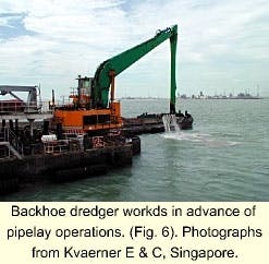
Because it was expected that some hard seabed material would be encountered, the selected dredger had to be effective at removing such material (Fig. 6).
The route had to be dredged from the shallows near the shoreline, down to a depth of 28 m in some places.
The dredger which was capable of satisfying all these constraints was a back hoe dredger mounted on a flat-bottomed barge that could move itself on spuds (legs).
In order to achieve the extended reach required for the deepest portions of the dredging work, an extra long arm was fabricated during the early stages of the project and was installed part way through to complete the deepest sections.
Kvaerner's main dredging and rock dumping subcontractor was Van Oord ACZ of Holland.
Pulling the bundle
After the route had been dredged to the required profile, the pull wire was laid in the trench from the linear pull winch on Jurong Island across to the launchway on Pulau Ular (Fig. 1).
The linear pull winch had a pull capacity of 350 tonnes force, and the pullwire had a safe working load in excess of 350 tonnes force. The maximum linear velocity when pulling is about 4 m/min, although this depends on local conditions.
Launch of the pipeline bundle occurred on Jan. 26, 2000, on Pulau Ular.
Flotation devices attached to the top of the pipeline bundle along its length increased its buoyancy and thereby minimized the pull force required (Fig. 7).
Several buoyancy devices were tested before use to select the best type. The most critical factor was that they not take in water when submerged because this would reduce buoyancy, making the bundle potentially too heavy to pull.
The buoyancy tanks were specially manufactured for the job from polyurethane foam with an outer waterproof plastic casing.
Because of restricted space on the shore ends of the pipeline, a riser had to be installed at each end so that the tie-in points for the eight lines would be as close as possible to the shoreline and fence line.
With the bottom of the risers below the water level, this meant that the entire bundle had to be lifted at the Jurong Island end so that the risers could be installed.
At the launch site on Pulau Ular, the preinstalled riser was pulled into position along with the rest of the bundle.
During the pull operation, the fiber-optic cables were tested on a number of occasions to ensure their integrity.
Commissioning
Upon completion of the pull operation, a hydrostatic test of each of the pipelines and continuity testing of the fiber-optic cables were carried out. Dumping of the filter layer was commenced after the successful completion of these tests.
When the dumping of the armor rock was completed, the final pipeline hydrostatic tests and fiber-optic continuity tests were completed satisfactorily.
The entire system was then handed over to Shell.
By completion in May, the following had been achieved:
- Dredging of 165,000 cu m of seabed.
- Installation by pulling of coated pipes weighing 4,000 tonnes.
- Installation of 53 tonnes of sacrificial anodes.
- Installation of 10 km of fiber-optic cables.
- 120,000 tonnes of sand-gravel backfill placed over the bundle.
- Laying of160,000 tonnes of armor rock laid to protect the bundle.
The total project duration was 15 months; the task was completed on schedule and on budget.
The author
Russell K Byfield is the regional manager of business development for Kvaerner E&C for the oil & gas sector based in Singapore. He has 14 years' experience in the sector starting with Mobil Oil Australia in refinery operations and planning followed by several years with Natco in the UK and Singapore designing oil and gas processing equipment for fixed and floating production facilities. He has been with Kvaerner for 4 years starting as a lead process engineer. Byfield holds a degree (honors) in chemical engineering from the University of Adelaide, South Australia, and is a member of IEAust.
