Method analyzes buckling for reeled insulated line pipe
A method has been developed that identifies critical parameters for reeling coated or insulated line pipe and thereby avoid local buckling at tie in welds.
Called a "Reeling Parameter Study," the method identifies the relative importance of these parameters and documents the effect of possible remedial measures.
Experience during reeling of pipelines with thick insulation coatings has shown that the combination of this type of coating with small changes of pipeline wall thickness or material properties across tie-in welds can, if handled improperly, result in unacceptable local buckling of the pipeline.
The problems became evident during mobilization for pipeline installation on the Åsgard field in 1998. Solutions were developed to avoid them through a finite-element analysis that simulates the behavior of a pipeline with a thick insulation coating subjected to plastic bending during reeling.
The analysis clearly showed that local buckling of the pipeline can and may occur for unfortunate combinations of pipeline design, coating thickness or stiffness, and reeling parameters.
Application of the method on projects during 1999, some with pipelines far more susceptible to buckling than those which buckled in 1998, resulted in the successful completion of pipeline installation for the 1999 season with no buckling incidents.
Asgard development
Coflexip Stena Offshore Norge AS (CSONOR), Lysaker, Norway, was awarded a contract by Statoil for installation of the majority of the infield flowlines for the Åsgard development, one of the world's largest subsea development projects. Total length of flowlines to be installed is approximately 160 km: about 100 km were installed in the 1998-1999 season; the remainder is to be installed during spring 2000.
The majority of the flowlines, about 140 km, is 10 in. nominal diameter; the remainder is 12 in. Two of the 12-in. flowlines are coated with thin-film coatings; the rest, with insulation coatings up to 55 mm thick in order to maintain the contents' temperature during operation or shutdown situations.
Most of the flowlines are fabricated from 13%Cr linepipe, a material not used previously for offshore pipelines except on the Gullfaks Satellite project for the same client in 1997. The qualification of the welding of this material for use with the reeling method is covered by Duthie.1
The insulated flowlines are prefabricated onshore into 950-m lengths at CSONOR's stalk fabrication yard in Orkanger, Norway. Immediately before offshore installation, these long lengths of pipe are welded together, an operation that takes place with the CSO Apache installation vessel moored at the yard.
Thick polyurethane field-joint coating is applied to the tie-in weld between the stalks and the completed section of pipe reeled onto the vessel. In this way, by repeating the tie-in operation for the appropriate number of stalks, the complete flowline is assembled before the vessel moves offshore. This method of flowline fabrication ensures that all welding and field joint coating is performed onshore in a well-controlled environment.
During the spooling operation for the 1998 installation season, several instances were observed of local buckling of the tie-in welds between prefabricated stalks. The affected welds had to be cut out and repaired offshore.
The pipes that buckled had all been designed in the traditional manner in which the wall thickness required for reeling is identified based on considerations of local buckling and ovalization of the pipe wall. The occurrence of local buckling of the tie-in joints was therefore an unwelcome surprise.
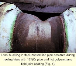
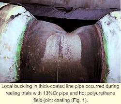
Full-scale testing of the bending of these pipes, to qualify the coating systems, had been performed before reeling. No significant buckling of the pipe was observed. Fig. 1 shows a typical local buckle, in this instance from full-scale testing in January 1999, in which conditions were deliberately set-up to provoke buckling.
Local buckling of the tie-in welds between stalks is unacceptable for the following reasons:
- Straightening of the buckled pipe may cause the weld to fracture resulting in a potentially dangerous situation.
- Offshore repair delays the vessel and leads to significant additional project costs.
- The buckling disturbs the natural lay of the pipe on the reel and reduces the total capacity of the vessel.
In the short-term, the buckling was brought under control by use of controlled back-tension during reeling and by the decision to stop using the polyurethane field-joint coating.
For long-term prevention, however, it has been necessary thoroughly to examine the various factors that may contribute to local buckling, identify their impact on the buckling process, and find documentable methods of bringing them under control.
Local-buckling theory
Various local-buckling theories have been developed and included in traditional rules for pipeline design.2 3 These theories have been used for the design calculations of the pipelines in question and have obviously been shown to be inadequate.
It has therefore been necessary to identify the areas in which the reeling of thick-coated pipelines deviates from standard practice and promotes buckling.
The following aspects of the design and fabrication method affect the tendency to local buckling:
- The use of thick stiff insulation coating on the pipeline together with a field joint coating that, at the time of reeling, has effectively no stiffness.
- Wall thickness and material property variations across a tip-in weld.
- Local reduction in pipeline material strength due to high temperature resulting from the use of post-weld heat treatment or a hot field-joint coating.
- Bending induced by the geometrical configuration of the installation vessels ramp and reel.
- The global stiffening of the pipeline during reeling resulting from the application of controlled back tension.
None of these aspects is covered by traditional local-buckling theories as included in the standard design rules. An alternative approach to the problem, which would assess the impact of the different input parameters, was therefore necessary.
The method selected was the use of non-linear finite element modeling.
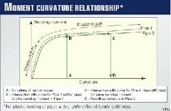
During reeling, the pipes are bent to a radius defined by the size of the hub of the main reel on CSO Apache. This involves significant plastic bending of the pipes. The bending moment in the pipe is plotted against the pipe curvature to yield a figure that defines an initially linear relationship between these two entities.
As the curvature is increased beyond the elastic limit of the material, the bending moment of the pipe approaches the fully plastic moment of the pipe and the curve moves from the vertical towards the horizontal. A further increase in curvature will produce little or no increase in bending moment.
If two pipe sections adjacent to each other have slightly different bending stiffness, their initial behavior will be similar and there will be little difference in curvature for the same bending moment.
As the bending is increased into the plastic region, however, the moment-curvature curves will diverge and the difference in curvature for the same bending moment becomes significantly greater. An unstable situation, leading to local buckling of the less stiff pipe, may develop.
It is this process (Fig. 2) that it is necessary to model with non-linear finite element methods.
Modeling of local buckling
For a reasonable understanding of local buckling, how the reeling process aboard CSO Apache influences it, and whether the finite-element modeling is giving reasonable results, three different models have been developed:
- A model of four-point bending of a 20-m length of flowline.
- A model simulating the bending rig as used for physical testing of the reeling process.
- A model simulating the actual geometry of the Apache during reeling.
The nature of the problem necessitated the analyses be performed with large deflection theory with full non-linear material behavior.
All analyses are performed with the non-linear finite-element program MARC and the associated pre and post-processor MENTAT.4
Four-point bending
Analysis of a pipe section subjected to four-point bending establishes the behavior of various pipe sections under constant bending moment. The center section of a beam subjected to this type of loading is in pure bending; the initial behavior of the beam can therefore readily be compared to simple theoretical predictions of beam-bending behavior.
This analytical model serves to check the finite-element modeling of the pipe cross-sections against the theoretical behavior of the actual structure.
The model does not impose any restraints to the development of pipeline buckling as a result of the reel geometry or applied axial tension during reeling. The results of the analysis of this configuration will therefore be overly conservative if used to predict buckling of pipe sections on Apache.
They will, however, give a very clear indication of the impact of changes in pipe configuration on its buckling behavior.
The analysis is set up so that it allows the behavior of alternative pipe sections to be evaluated. The pipe configurations analyzed are as follows:
- Bare pipe.
- Pipe with full coating (~50 mm thick); the steel and coating are modeled by two sets of shell elements on top of each other with the same nodes; steel behavior for 13%Cr modeled including plasticity; coating pure elastic.
- As immediately previous, but with 300 mm with no coating to simulate field joint at right hand end of model, equivalent to a 600-mm field joint at the center of the 20-m span.
Model; results
The FE model is assembled from shell elements modeling the flowline and coating.
Symmetry is exploited so that the model effectively simulates the bending of a 20-m long section of pipe. The effect of axial tension on the pipe-bending behavior has not been considered for this model.
The analysis is performed by application of a vertical deflection to the centerline of the pipe 2 m from the left end of the model. Small load steps are used with a maximum deflection which would give a vertical section of pipe at the left end of the model.
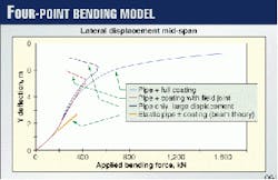
Fig. 3 shows the global deflection behavior of the 20-m span: The center deflection of the span is plotted against the applied bending force. This figure shows two straight lines describing the theoretical response of a span based on standard beam theory.
The results of the FE analyses in the elastic region agree well with this theory, as can be seen from the plot. Once the elastic limit has been exceeded, the deflection increases more rapidly until geometric effects result in a further increase in stiffness.
Up to a central deflection of 4 m, the three models analyzed behave similarly. The elastic stiffness of the coated pipe, with or without a field joint, is slightly (~3%) greater than that of the bare pipe.
When the central deflection reaches approximately 6 m for the bare pipe, the force required to give further deflection drops because the pipe has buckled. For the coated pipe, there is no indication of such behavior; the force required for further deflection increases as a result of geometrical effects. Inclusion of a field joint, however, results in buckling for a deflection of ~5 m.
Buckling of coated pipe with a field joint is therefore demonstrated for lower loads and deflections than for uncoated pipe. This reduction in buckling capacity results from the large change in stiffness that occurs between the coated pipe and the uncoated pipe when the pipe is bent plastically.
The continuing elastic behavior of the coating means that the effective step change in bending stiffness increases with increasing plastic strain in the pipe.
A useful measure of the performance of a pipe during reeling is the development of ovalization with bending. In this article, the definition of ovalization or out-of-roundness follows Det norske Veritas (DnV).2
The existing literature also presents some data and empirical formulas relating the development of ovalization to bending, for example, BS8010 and Bai.3 5 This allows some independent verification of the results of analyses performed as part of this work.
The results of the finite-element analysis agree well with those obtained from these references.
It may be concluded from the analysis based on this model configuration that, although accurate predictions of the buckling behavior on Apache cannot be made, because of the different boundary conditions, it is possible to obtain an indication of the relative susceptibility of different pipe configurations to buckling.
Models that simulate the actual conditions during reeling are, however, considered essential if the real behavior of the pipe on Apache is to be predicted accurately.
Bending rig
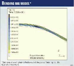
To remove the conservatism included in the results from the Four-Point Bending model, further analysis has been performed on a finite-element model that simulates the geometrical configuration of a bending test rig, such as that operated by Herriot Watt University, Edinburgh (Fig. 4).
This model allows prediction of the development of buckling due to bending of the pipe around a constant radius. Because of the geometry of the rig and the boundary conditions imposed on the model, the loads acting on the pipe, especially the shear force necessary to generate the plastic bending of the section, are significantly different from those that occur during reeling onto Apache.
The model may, however, be used to predict the tendency towards buckle development.
The pipe model is the same as that described previously for the Four-Point Bending analysis. Rigid surfaces, of the same radii as the reel and straightener of CSO Apache, model the reeling and straightening surfaces of the bending test rig. Automatic contact algorithms are used to define the interface between the surfaces of the rig and the surface of the pipeline.
These surfaces are deflected into the pipeline rather than the pipeline being forced to bend round the surface, as is the case in a bending test rig. The effect of tension on the bending process may be modeled analytically, although it is very difficult to include this in physical testing in the rig.
Buckling development
The analyses performed for this model configuration have demonstrated the buckling of pipes during bending around a fixed-radius former that is essentially similar to the bending in a test rig.
Fig. 5 shows a plot of the deformed shape of the pipe for a typical analysis. The pipe has lifted off the surface of the bending former at the field joint, and significant localization of bending, with attendant increase in ovalization, has occurred.
This plot also illustrates the essential difference between the numerical model and the normal test-rig configuration. In the analysis, the left end of the pipe is free to lift from the former; this is impossible in a test rig because the pipe is held firmly at this location.
Development of buckling will therefore be restrained, to a greater or lesser extent, by the test rig boundary conditions.
The analysis of the bending-rig configuration has shown the importance of performing an analysis that, as close as possible, reflects the actual geometry and boundary conditions found on the vessel.
Further development of a model accurately to reflect the reeling situation on Apache has therefore been performed.
Apache model
The models thus far described do not present a realistic picture of the bending processes as they occur during reeling onto Apache. These models may therefore be inadequate when used to predict local buckling or to quantify the localization of bending during reeling.
Fig. 6 shows the vessel CSO Apache during loading of pipe at Orkanger, Norway. The Apache model has been developed to simulate as closely as possible the actual geometry of the vessel.
The reeling process is modeled by dragging an initially straight pipe around a surface of the correct radius. This model is considered to simulate closely the conditions to which the pipe is actually exposed during reeling.
The pipe model is assembled from a combination of shell elements modeling the critical parts of the pipeline and its coating and of the elastic-beam elements modeling the section of pipeline closer to the aligner where it is only subjected to elastic bending.
The beams are attached to the end of the shell model by a series of link elements in order to give the correct transfer of loads and deformations at this location. The same method of modeling the pipe and coating is used as described previously for the Four-Point Bending model.
The model includes surfaces representing the reel and the aligner-straightener-tensioner arrangement on the ramp. The distance between these surfaces well represents the actual conditions on Apache. The rotation of the pipe is forced to a slope of 20° through the ramp to model the vessel configuration during reeling.
The surface of the reel is modeled over a 120° segment; the reeling of pipe is modeled by the end of the pipe model being dragged in a circular arc around this surface.
Back tension during reeling is applied by a point load at the free end of the elastic beam part of the model. The tension therefore contributes to the overall stiffness of the pipe during the reeling simulation.
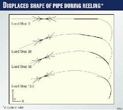
The duration of the analysis is arbitrarily set to 1 sec, with 120 load steps. The total rotation of the end of the pipe around the reel is 120°. The effective rate of loading is therefore 1° per load step. Fig. 7 shows the model configuration for load steps 0, 20, 60, and 120.
Variations; results
The analyses performed to investigate the 1998 buckling incidents have considered variations in the following parameters:
Fig. 7 shows the global behavior of the pipeline during reeling and how the pipe deflects vertically upwards between the ramp and reel and maintains this configuration as the right end of the model is pulled around the reel.
As the analysis progresses, it is possible to see the top of this span moving up and down in a fashion similar to observations from the vessel.
Buckling of the pipe develops at the field joint in the analyses with coating and a field-joint but no back tension. Use of back tension controls the extent of buckling.
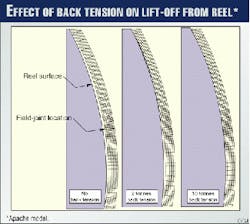
Fig. 8 shows three plots of the deformed mesh of the model. With no back tension, a clear gap exists between the pipe and the surface of the reel. Application of 2 tonnes back tension has reduced this gap significantly; with 10 tonnes, it is no longer visible.
A gap of this type, due to the pipe lifting off the surface of the reel at an uncoated or polyurethane-coated field joint, is unacceptable from practical considerations of reel packing, even if the strain levels and ovality are within acceptable limits.
The modeling of a fixed ramp angle of 18° during reeling has the effect of creating a stiff prestressed span between the ramp and the reel.
This influences the behavior of the pipe during reeling. Development of curvature in the field joint location is irregular in form. This behavior results from the energy locked into the span from the ramp rotation causing the step-wise development of plastic bending in the pipe on the reel.
With increased back tension, the irregular behavior is reduced but by no means eliminated. Of concern here is the step-wise development of the curvature with reeling, the process is obviously unstable so that only minor variations in conditions, such as a small change in wall thickness across the joint, could result in significantly higher curvatures, possibly leading to full buckling of the pipe cross-section.
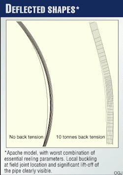
Fig. 9 shows the deflected configuration of the pipe for the analysis performed with
With no back tension, a clear buckle can be seen to develop as a result of the reeling process. The deflected shape with 10 tonnes of back tension illustrates the reduction in lift-off that results because of the application of controlled back tension.
Significant concentration of bending still occurs, however. Excessive back tension would further reduce the tendency to buckle but may result in unacceptably high ovality in the pipe.
Buckling detection
Analysis of the reeling of Åsgard 1998 thick-coated pipe onto Apache has shown that the tendency to develop buckling during reeling can be detected by use of non-linear finite element methods.
The change in stiffness, due entirely to the presence of an uncoated or polyurethane-coated field joint between stalks, is such that local buckling of the pipe will occur if remedial measures are not taken.
Application of axial tension during reeling reduces the tendency to buckle but does not eliminate increases in local curvatures, ovality, or plastic strains.
This sensitivity of the pipe to buckling is confirmed by the analyses performed where the effects of the coating are combined with a variation in wall thickness of
Clear buckling is apparent (Fig. 9) with an effective rotation of the pipe through ~20° because of development of a plastic hinge in the field joint. In this case, application of 10 tonnes of back tension is insufficient to control the development of buckling.
Variation of the wall thickness by
Parameter studies
To eliminate local buckling in field joints for current and future projects that involve the reeling of thick-coated pipelines, a "Reeling Parameter Study" (RPS) will be performed. This allows the impact of the various key parameters on the reeling operation to be assessed.
Where necessary, such a study will be combined with physical testing of the bending process. The emphasis will be placed on the calibration of the numerical modeling. It is also critical to obtain good input data for the analysis, such as the variation of non-linear stress-strain curves for pipe and coating materials with temperature.
For cases in which the need for this evaluation is questioned, the initial analysis may be performed using the simple Four-Point Bending model. This will give clear indications of the susceptibility of the pipe to local buckling.
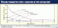
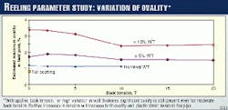
Figs. 10 and 11 show typical results from an RPS, including the variation of the separation of the centerline of field-joint from the reel and the degree of ovality in the pipe, with various levels of back tension.
Curves represent constant wall thickness and variations in wall thickness across the tie-in weld of ~5% and ~10%. It may be seen that by, in this instance, limiting permissible variations in wall thickness to ~5% and applying 10 tonnes of back tension, separation from the reel may be eliminated.
There is still, however, a concentration of bending as shown by the higher level of ovality. To eliminate this fully, an instant cold-field joint is required that has the same stiffness as the rest of the pipeline coating. Such a system is not, to the author's knowledge, available today.
Use of the RPS method, whereby the critical parameters during reeling are identified, their relative importance established, and the effect of remedial measures documented, means that it is now possible to prevent reoccurrence of local buckling problems on future projects.
This has been confirmed by the successful completion by CSONOR in 1999 of a number of pipeline-installation projects. Several of these had diameter, wall thickness, material, and coating configurations which resulted in pipelines far more susceptible to buckling than those which buckled in 1998.
As a result of the use of the Reeling Parameter Study method, and the elimination of hot field joints, no buckling incidents occurred during the 1999 installation season.
Acknowledgments
Thanks are due David Haldane at Herriot Watt University, Edinburgh, and members of the Åsgard project teams from both CSONOR and Statoil for their input.
References
- Duthie, S.A., "Qualification of Weldable Modified 13%Cr Stainless Steel Linepipe for Reelship Installation," Offshore Technology Conference, Houston, May 4-7, 1998.
- Det norske Veritas: DnV Rules for Submarine Pipeline Systems, 1996.
- BS 8010, British Standard, Code of Practice for Pipelines, Part 3, Pipelines subsea: design, construction and installation, 1993.
- MARC & Mentat User Documentation, MARC Analysis Research Corporation, Palo Alto, Calif., 1997.
- Bai, Y., Igland, R., and Moen, T., Collapse of Thick Tubes under Combined Tension and Bending, Journal of Construction Steel Research, Vol. 32, 1995.
The Author
Tim Crome is the structural design supervisor for the Norwegian branch of Coflexip Stena Offshore, Lysaker, Norway. He was employed 1980-86 by JPKenny in London, The Hague, and Oslo.
Following a period with Det norske Veritas (DnV), Crome joined the independent consultants Offshore Design AS, Oslo, where he was employed until 1997. Crome graduated from Imperial College, London, with a BSc (1980) in civil engineering.
