Advanced hydraulics analysis optimizes tricone bit performance
A high-pressure drilling simulator, aided by computational fluid-dynamics analysis, shows that penetration rates and hole-cleaning properties can be improved through the realignment of bit nozzles.
Factors that govern tricone bit performance include a nozzle system capable of cleaning the cones and wellbore as well as evacuating drill cuttings from under the bit.
In contrast to conventional design, the orientation of this nozzle system serves to:
- Clean the cones with a grazing hydraulic flow.
- Impact the borehole from a vertical orientation.
- Clean the cuttings from the center of the bit then radially outward.
Early work
Early rolling cutter bits, such as those invented by Howard Hughes in 1908, used drilling fluids to clean the cones, directing low velocity fluid toward the cones through large water-course holes. In 1948, advancements in this concept followed when Nolley, et al., reported on a rolling cutter bit that accelerated drilling fluids through nozzle orifices.1
In 1964, Feenstra and Van Leeuwen then described the conceptual differences of "bit balling" and "bottom balling."2
Bit balling occurs from the production of powdered rock material that sticks to the teeth of the bit, preventing the penetration of new rock. As rock material builds up on the cone, this phenomenon reduces the effective projection of the teeth where the build up between the teeth supports a large portion of the bit weight.
Bottom balling on the other hand consists of a layer of pulverized rock material that covers the borehole bottom, forming a plastic and pliable interface between the drill bit and untouched formation. This layer prevents the teeth from cutting new rock.
Workers at this time recommended directing nozzles at the cones to combat bit balling and directing nozzles at the borehole to combat bottom balling.2
In 1985, Slaughter reported on a bit design that directs drilling fluid through the nozzles in order to skim the leading edge of the gauge-cutting elements of the cones before impacting the borehole.3 Next, in 1992, Moffitt, et al., described tests in which a variety of nozzle targets, similar to Slaughter's original directed nozzles, were evaluated.4
Subsequently, a more optimum nozzle target was selected, which improved field penetration rates by up to 50% over conventional nozzle orientation.
In turn, Pessier describes a third cone-cleaning nozzle system that became available in 1996.5 This nozzle is positioned so that the drilling fluid passes between the gauge-cutting surfaces and the borehole wall on the trailing side of the cone, located in the gap created by cone offset (skew angle).
In all the nozzle configurations described above, the fluid is generally aimed toward the corner of the borehole, with the nozzle orifice located somewhat inboard from the borehole wall and the hydraulic stream directed radially inward. Thus, the nozzle orientation directs the fluid downward and outward, into, or slightly above the corner of the borehole.
A new approach
New evidence indicates, however, that nozzle orientation should instead impact the borehole considerably inboard from the wall of the hole. In essence, nozzle design should be oriented to skim the trailing side of the cones so that it impacts the borehole bottom.
After impact, the fluid and cuttings can then be diverted outward toward the borehole wall and upward past the bit body.
For reference purposes, each nozzle configuration will be referred to as follows:
- Type A-Conventional nozzle.
- Type B-Original directed nozzle (Slaughter).
- Type C-Second generation directed nozzle (Moffitt).
- Type D-Directed nozzle (Pessier).
- Type E-New nozzle system.
New nozzle system
The Type E nozzle elements, consisting of two configurations, aim to:
- Point the nozzle stream so multiple rows of the cone are cleaned.
- Orient the jet so the impingement point on the bottom of the hole is located substantially inboard from the borehole wall, diverting the fluid outward.
To achieve the first configuration, the fluid stream of the nozzle passes close to, and thereby cleans, multiple rows of cutters on the cone.
In comparison, most of the previous cone-cleaning nozzle orientations direct the nozzle fluid toward the gauge. As a result, the fluid cleans only the gauge-cutting elements.
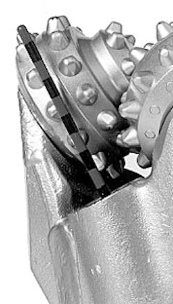
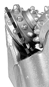
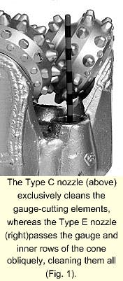
A close up comparison of the nozzle trajectory of Types C and E bits provides evidence that the Type C nozzle cleans the gauge-cutting elements alone (Fig. 1). Conversely, the Type E nozzle passes the gauge and inner rows of the cone obliquely, cleaning them all.
For the second configuration, the jet stream of the Type E nozzle configuration is oriented more or less parallel to the wall of the borehole at a distance positioned somewhat inboard from the borehole wall. This causes the fluid to impinge on the bottom of the borehole and then flow outward toward the borehole wall.
Next, the fluid diverts upward toward the surface. The fluid follows one continuous motion, which efficiently evacuates the cuttings off bottom. The fluid stream generated by all other nozzle orientations (Types A-D) either obliquely impacts in the corner or on the borehole wall above the corner.
The curvature of the borehole then diverts the fluid inward toward the center of the bit. Tests proved this is an inefficient way to evacuate cuttings from under the bit.
Development
The Type E nozzle position was discovered and developed through a series of laboratory tests in which dozens of different nozzle orientations were evaluated. The rates of penetration (ROP) of full size bits with different nozzle orientations were conducted in Hughes Christensen's high pressure drilling simulator.
All tests reported used 77/8-in. IADC 517 type bits drilling in Mancos Shale with 4,500 psi of bottomhole pressure. The bits were jetted with three 10/32-in. diameter nozzles.
The drilling fluid consisted of a 9.2-ppg chrome lignosulfonate mud circulated at 280 gpm. Tests were conducted with two sets of drilling parameters: 90 rpm and 45,000 lb, and 225 rpm and 40,000 lb.
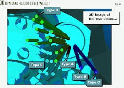
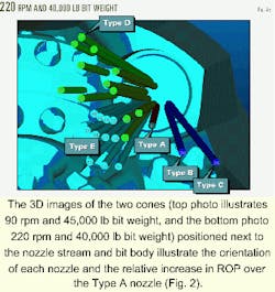
Figs. 2a and 2b illustrate the orientation of each nozzle and the relative increase in ROP over the Type A nozzle. Thus, the numbers on the cylinders represent the relative penetration rates obtained in the drilling simulator tests as compared to the Type A nozzles (denoted as 0).
Additionally, these illustrations show 3D images of the two cones positioned next to the nozzle stream and bit body as viewed from below the bit. The cylinders in the figures represent the location and orientation of the various nozzle positions tested.
Most of these data come from one test bit that has a special nozzle that is easily oriented. Engineers obtained data for the Types B and C bits, however, by running bits built with these nozzles. The cutting structures of all the IADC 517 bits were virtually identical.
Data shown in Figs. 2a and 2b typically represent penetration rates taken from single test runs. Yet in three cases, tests were repeated to assess the statistical uncertainty in the data, showing that the standard deviation for these relative ROP numbers is about 7.5 for the 90-rpm data and 5.2 for the 225-rpm data.
Additionally, this figure confirms the results that bits with Type B nozzles drill somewhat faster than bits with Type A nozzles.3 4 Also, bits equipped with the Type C nozzle configuration drill faster than Type B.
In Figs. 2a and 2b, there are several nozzle locations in the vicinity of the label that identify a region of Type E nozzle locations. These nozzles were found to drill substantially faster than all other types.
Basically, the trailing side of the cone binds one side of this region while a dramatic drop in ROP marks the opposing side of this region. The intermesh of the cutting structure determines the inner boundary, and ROP drops off less dramatically as the jet is positioned closer to the borehole wall.
In addition to ROP, cone erosion must also be considered when selecting the optimal nozzle orientation in the Type E region. As the jet is positioned closer to the cone, erosion necessarily increases. Thus, a balance must be sought that maximizes ROP and minimizes cone erosion.
CFD analysis
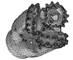
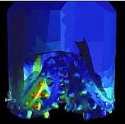
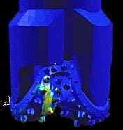
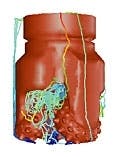
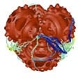
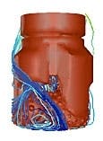
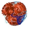
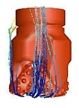
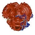
Computational fluid dynamics (CFD) simulations were performed to model the flow around Types A, D, and E bits and to evaluate each bit's ability to clean the cone, borehole, and borehole bottom under the bit. CFD was also used to quantify the cone erosion potential for Type E nozzles and to select a nozzle position with minimal cone erosion potential (Fig. 3).
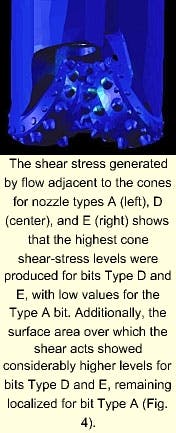
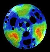
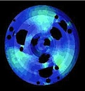
The shear stress can be taken as a measure of the capacity of the flow adjacent to a surface to dislodge debris through the application of a tangential force. Fig. 4 shows the shear stress generated by flow adjacent to the cones for nozzle Types A, D, and E. Fig. 4 also shows the highest cone shear stress was produced for bit Types D and E, while that for the Type A bit is very low.
The surface area over which the shear acts is also considerably larger for bit Types D and E and is very localized for bit Type A. In a similar manner, the extent of shear produced along the hole bottom is a measure of the capacity of the flow from the nozzles to clean the borehole.
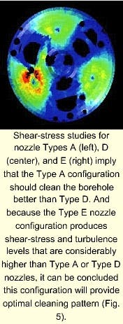
Fig. 5 shows the shear stress produced on the borehole bottom for Types A, D, and E bits, respectively. The shear produced by configuration Type A is higher than that produced by Type D.
This implies that the Type A configuration should clean the borehole better than Type D. This result was further substantiated by laboratory tests that showed Type A bits drill faster under bottom-balling conditions than Type D bits.
Note that the greatest bottomhole shear stress levels are generated by nozzle configuration Type E.
In summary, because the Type E nozzle configuration produces shear stress and turbulence levels that are considerably higher than those produced by either Type A or Type D nozzles, it can be concluded that this configuration should provide better bit and hole-cleaning properties.
This improved cleaning should improve performance in both bottom-balling and bit-balling environments because the Type E configuration has the highest levels on both the cones and the bottom of the borehole.
Cuttings evacuation
Cuttings evacuation was simulated by numerically injecting simulated 0.2-in. diameter dolomite particles, having a density of 174 lbm/cu ft, into the flow field. A total of 35 particles were released from seven discrete injection locations, covering a wedge-shaped portion of the borehole bottom between two cones, and allowed to be transported by the turbulent flow field.
Traces showing the paths taken by the injected particles during a 0.15-sec interval are shown in Fig. 6. The results show that Type A nozzle configuration swept the majority of the particles off bottom toward the center of the bit. From this point, they proceeded upward in a plume between the cones into the cavity between the bottom of the bit body and the top of the cones.
From there, the particles attempted to escape between the legs of the bit, but most became re-entrained into the downward flow from the nozzle. Of the 35 particles originally released into the flow of the Type A bit, only 1 particle escaped above the bit within 0.15 sec, or about the time required for the fluid to exit.
On the other hand, Type D bits swept about half of their particles outwardly then up and away from the bit. The other half was then swept toward the center where they were circulated and re-entrained like those of the Type A bit.
With the Type D nozzle configuration, 15 of the original 35 injected particles escaped from below the bit within 0.15 sec. Finally, the enhanced impingement location of the Type E nozzle configuration forced a majority of its flow outward, away from the cutting surface, carrying most of the particles on bottom directly upward and away from the bit bottom.
For the Type E configuration, 25 of the original 35 simulated particles escaped from under the bit in 0.15 sec.
Cone erosion
Nozzles positioned for cone cleaning also have the potential to erode the cones. Small changes in the relative position of the nozzle stream and the cone shell can make a large difference in this erosive tendency.
Generally, ROP increases as the nozzle stream moves closer to the cone shell. However, cone erosion also increases at the same time.
CFD was used to quantify the erosive tendency of several of the positions shown in Figs. 2a and 2b. Type E nozzle positions were selected that maximized ROP and minimized erosive tendencies.
Field data
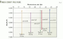
More than 300 bits with Type E nozzles have been tested in six sizes and types in field operations. The case study for this article, in Panola County, Tex., was selected because bits with all five nozzle types were run with similar drilling practices, by one drilling contractor (Mustang Drilling Inc.) working for one operator (R. Lacy Inc.) in a localized area.
The 21 bits in the case study drilled about 2,000 ft of sandstone and shale before dulling into the Travis Peak. All were run on rotary assemblies at 70 to 80 rpm, with a bit weight of 40 to 45,000 lb, and 6-7.5 hydraulic hp/sq in. with about 10.7 ppg mud.
Fig. 7 shows the average ROP for these bits where the horizontal axis represents ROP and the vertical axis represents depth. The average of several bit runs is shown as a vertical bar.
The ranking of ROP for the five different nozzle bit types corresponds relatively well with that predicted by laboratory tests shown in 2a, except that Type B bits drilled faster in the field than expected. Considering the standard deviations of the test and field data, there is good correlation between these data both in rankings and magnitude.
This graph shows Type E bits drill faster than all other types. Considering the averages and standard deviations, the average ROP of the Type C and Type E bits are the two that are most likely to be statistically equivalent.
A "t" test of the means of Type C and Type E indicates the difference between Type E and Type C bits is statistically significant to a confidence level of 97%.
The ranking of ROP for the five different nozzle bit types corresponds relatively well with to that predicted by laboratory tests shown in Fig. 2a, except that Type B bits drilled faster in the field than expected.
Considering the standard deviations of the test and field data, there is good correlation between these data both in ranking and in magnitudes.
References
- Nolley, J.P., Cannon, G.E., and Ragland, D., "Results Obtained with High-Nozzle-Fluid-Velocity Rotary Bits," presented at the Eighth Annual Convention of American Association of Oilwell Drilling Contractors, Houston, Oct. 11-13, 1948.
- Feenstra, R., and Van Leeuwen, J.J.M., "Full-Scale Experiments on Jets in Impermeable Rock Drilling," Journal of Petroleum Technology, March 1964.
- Slaughter, R.H., "Development, Laboratory and Field Test Results of a New Hydraulic Design for Roller Cone Bits," SPE paper 14220, presented at the 60th Annual Technical Conference and Exhibition, Las Vegas, Sept 22-25, 1985.
- Moffitt, S.R., Pearce, D.E., and Ivie, C.R., "New Roller Cone Bits with Unique Nozzle Designs Reduce Drilling Costs," SPE paper 23871, presented at the IADC/SPE Drilling Conference, New Orleans, Feb.18-21, 1992.
- Pessier, Rolf, C., "Biased Nozzle Arrangement for Roller Cone Bits," US Patent Pending.
The authors-
Roy Ledgerwood is team leader of the Drilling Mechanics Research Group at Hughes. He has authored several publications relating to poro-elastic plastic modeling of tooth indentation processes, assessment of rock drillability from logs, and measurement and optimization of tricone bearings using 3D finite element analysis and reliability analysis applied to bearing life prediction.
Ledgerwood holds a BS in mechanical engineering from Texas Tech University and an MS in mechanical engineering from Rice University.
Brian Wiesner is a senior engineer at Hughes Christensen. He is responsible for designing soft formation elastomer seal tricone bits. Wiesner started with Hughes Christensen after graduating from the Colorado School of Mines in 1995, where he received a BS in engineering with a specialty in mechanical engineering and a minor in metallurgy.
Tommy Harris is a research engineer for Hughes Christensen. His responsibilities include contributing to the design of PDC drag bit drilling models and solid body rendering of roller cone bits. Harris joined Hughes Christensen in 1988 after receiving a BS in mathematics from the University of Houston.
