Modular construction of catalyst-regen unit saves time, costs
As part of the work associated with its 540,000 b/d Jamnagar, Gurajarat, India refinery, completed in 1999, Reliance Industries Ltd. (RIL) installed the catalyst-regeneration section of its reforming unit in prebuilt modules.
Early in the development of the project, UOP presented the advantages of modular construction for the 85-m tall catalyst-regeneration section to RIL and Bechtel Corp.'s office in London. RIL and Bechtel agreed that this approach was the best way to shorten the schedule and reduce costs while maintaining quality.
The three companies also agreed that the off site fabrication of the modules should be carried out in India, as proximity would yield efficiencies in cost and quality. UOP chose Larsen & Toubro Ltd. (L&T), Mumbai, as the fabricator based on its experience in large projects.
This was the largest module-approach project undertaken by UOP to date. RIL and its contractors completed the module installation at the construction site without any major issues.
Construction challenges
The reforming unit of the Jamnagar refinery uses UOP's Platforming process. The catalyst-regeneration section, which uses a UOP technology called Cyclemax CCR (continuous catalyst regeneration), has a catalyst-circulation capacity of 4,500 lb/hr.
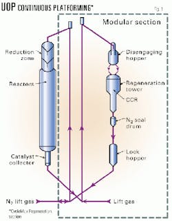
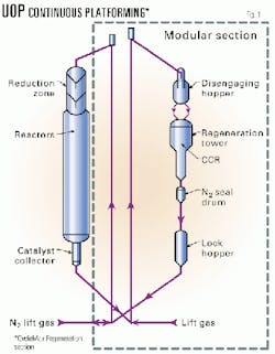
The catalyst-regeneration section of the Platforming unit is the world's largest Cyclemax CCR application, towering 85 m above grade (Fig. 1).
The nature of the process requires the equipment to be positioned in series and in a "flow-down" fashion, resulting in a relatively narrow, "high-rise" process unit. The unit required more than 400 instruments, special metallurgy for piping and vessels, and operating temperatures greater than 500° C. These combined issues posed many obstacles to conventional construction techniques.
Whether the CCR section was modularly or conventionally built, several inherent challenges included:
- A large height-to-width ratio of the structure.
- A large number of high temperature and stress-critical process piping loops and equipment.
- Stringent layout requirements of piping, equipment, and instruments for process reasons.
- The need to have a user-friendly layout at lower decks, where equipment, piping, and instrument density is high.
Construction planning for the Jamnagar refinery project also had to consider a potential shortage of skilled labor for complex units.
Plans for modular approach
In third quarter 1996, senior executives of RIL visited UOP to discuss various aspects of the project implementation. The construction method for the "high-rise" CCR section was discussed at length.
Several key issues led to the choice of modular construction:
- The modular approach minimizes the number and sizes of required cranes. It also shortens the erection time from several months to several days.
- Module assembly at grade allows simultaneous access to all parts of the CCR section for construction and inspection activities. The conventional approach requires all its activities to be carried out in a "from the ground up, piece-by-piece" fashion.
- Conventional construction activities at high elevation can affect the quality of fabrication and nondestructive tests, such as radiography of pipe welding.
- Pressure testing in the shop virtually eliminates any field-pressure testing.
- It is easier to perform inspection and rectify deficiencies at the assembly site than at the construction site.
In optimizing module dimensions, UOP considered the capacity and reach of available cranes and the strength of the module's structural frame for lifting and safety in handling.
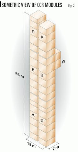
The modular CCR section consists of twin towers of equal height. Each tower has three modules, designated A, B, C or D, E, F. One side module, G, bridges the two towers. Fig. 2 depicts this arrangement.
In one of the two towers, a stairwell provides access for both the CCR and the reactor section. Running parallel to the stairway and supported laterally by the towers is a lift with step-outs at various levels to the CCR structure.
The largest and heaviest modules, A and D, at grade level, weigh more than 200 tonnes each and have a length of approximately 31 m. All except module G have an overall cross-sectional dimension of approximately 6.5 m wide by 7.3 m high. The lightest are top level modules C and F, each weighing about 70 tonnes. The total weight of the CCR modules exceeds 900 tonnes.
Local contractor
Prior to actual award of the project, RIL requested that UOP carry out a feasibility study for fabrication of the modules in India. RIL had several chief considerations in mind: reducing transportation costs, minimizing risks and damage to the modules, and better after-delivery service by the local module fabricator.
With the help of UOP's worldwide subcontracting and procurement database and logistical support by UOP's liaison office in New Delhi, the proposal team engaged in review and inspection activities to qualify Indian companies for the project.
UOP teamed up with L&T, one of the largest engineering, procurement, and construction (EPC) companies in India. The chemical plants and systems, group II, division of L&T has had extensive experience in petrochemical and refining projects in India. They have also executed various projects for RIL in India.
L&T's world-class fabrication facility was of particular importance for this project. It had a waterfront and jetty for sea-going vessels, which could accommodate the number, size, and weight of the modules.
Detailed design
Based on its experience in designing and fabricating modular CCR units, UOP prepared a front-end engineering design (FEED) package for the detailed designer. This package gives the EPC contractor a good starting point for the design. It contained:
- Mechanical flow diagrams.
- General arrangement of equipment and major piping circuits.
- Various design, fabrication, and construction-related specifications.
- A framework of project-specific inspection and testing plan.
- Other design instructions necessary for a given project.
For example, UOP provided front-end structural design and piping flexibility analyses for critical piping loops in the FEED for this project because of the complexities as a result of the size of this particular CCR section.
For a smooth transformation of the FEED package into a detailed engineering package, UOP and L&T design teams worked closely together. UOP maintained a resident team at L&T offices. Additionally, specialists from UOP's main office in Des Plaines, Ill., were dispatched periodically to L&T offices for specific discussions and reviews.
The two companies discussed and reviewed the equipment arrangement and piping layout in depth. L&T reanalyzed the stress-critical piping loops to finalize routing. The front-end structural design package enabled L&T to complete the structural analysis and design of the main skeletal members early, which in turn, enabled timely procurement of long-lead structural members by UOP outside of India.
Use of up-to-date design software ensured a high level of accuracy and timely completion of detailed engineering.
Chief among them were PDS (by Intergraph) for modeling equipment, piping, and structural steel; STADD III for structural design; and CAESAR II for pipe stress analysis.
UOP and L&T also used the ANSYS package for finite element analysis of the baseplate assemblies and the X-Steel package for automatic steel-fabrication drawings.
UOP and L&T jointly analyzed the PDS model to ensure compliance with various design, operational, maintenance access, and safety requirements.
Procurement strategy
UOP has developed relationships with certain equipment manufacturers specifically for critical equipment employed in the CCR section. These manufacturers have a good understanding of the equipment requirements stipulated in UOP's basic process design package.
UOP and L&T split the procurement of all equipment and instruments to optimize UOP's relationships with CCR equipment suppliers and L&T's relationships with local suppliers.
UOP supplied the regeneration tower, electric heaters, regeneration blower, dust collector, and all critical instruments. It also supplied structural steel sections for major skeletal members not available in India. It is worth mentioning that all heavy W14 wide flange sections used as columns were rolled to design lengths, thus avoiding the cumbersome splicing.
L&T supplied the remaining equipment and bulk materials that were available locally. These included the remaining fabricated pressure vessels, blowers, and pumps, as well as all electrical and instrumentation (E&I) equipment, insulation, and piping raw materials.
To ensure the uniform quality of equipment and materials purchased both locally by L&T and internationally by UOP, the two companies jointly developed technical and quality assurance and quality control (QA/QC) requirements in the form of technical requisitions and inspection test plans (ITP).
Fabrication and QC
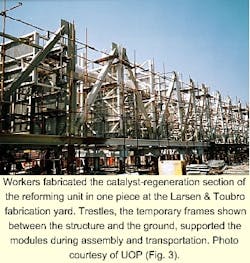
The CCR section was fabricated horizontally, or 90 degrees off from the normal erected position, as a single structure with predetermined module breaks (Fig. 3). Workers routed all piping circuits through the modules and connected them to the equipment and vessels.
The result was a completely assembled CCR section in the horizontal position. This approach guaranteed exact fit of all pieces upon disassembly of the structure into individual modules.
Early planning and training of supervisors and workers helped overcome the perceived difficulties of this unusual construction method. Training also identified the nuances of the CCR section as well as normal construction considerations.
To this end, the UOP resident team and L&T design engineers formed a team and moved to the L&T fabrication shop in Surat, Gujarat. This team had several major responsibilities:
- Timely installation on modules of critical-path equipment and components manufactured and fabricated elsewhere.
- Fabrication and assembly of modules complete with structural framework, piping circuits and pipe supports, lighting fixtures, electrical heat tracing, E&I cables, piping and equipment insulation, and complete painting system.
- Maintenance of precision in fabrication to ensure structural, piping, and E&I fit-ups at Jamnagar site.
- Schedule control and development of recovery plan.
- Implementation of inspection-test plan activities.
- Compilation of manufacturers' record books for fabrication and testing-related documents.
When the horizontal assembly was complete, UOP Technical Services visited the module assembly site and inspected the CCR for conformance with design. RIL also examined the unit for operating and maintenance requirements prior to shipment to the site.
UOP and L&T generated detailed indices of the manufacturers' record books, covering all inspection and testing requirements of equipment fabrication and module assembly. RIL and Bechtel approved these.
During the whole course of the project, these indices served as the road map for all QA/QC-related activities from suppliers' shops to the module assembly site. Therefore, QA/QC-related documents such as test procedures, welding procedure specifications and procedure qualification records (WPS/PQR), material test certificates, and traceability records were secured and incorporated into the manufacturers' record books with much ease.
These completed records allowed for a smooth sign-off of the ITP by UOP and L&T at the time of module delivery to RIL.
Module shipment
Preparation to ship the modules consisted of three work items. First, workers had to separate the modules and interconnecting components at the module breaks. Piping circuits were cut at the module breaks after the completion of hydrotest.
Cable-tray splice pieces were removed as ship-loose items, and grounding jumpers were disconnected at the module breaks. Cables that cross the module breaks were disconnected from the users, coiled, and fastened for shipment.
Lacing angles, connecting the neighboring modules at both vertical and horizontal planes, were removed and tagged for shipment. Finally, structural bolts at module breaks connecting the cap plates of the columns from the higher and lower modules were removed, allowing the structural framework of the module to be separated.
In parallel to the separation operation, workers added temporary supports to ensure safety during transportation and lifting. Fragile components such as stainless steel surfaces, transmitters, and gauges were protected against potential attack by seawater.
The third preparation component was the safety check. Before hydraulic trailers started moving the module from the assembly site, safety engineers rechecked all new and existing temporary supports for tightness and effectiveness, considering not just the horizontal shipping position but also the tilting from horizontal to vertical position during lifting.
All modules were checked for and cleared of any loose, foreign objects such as tools, which might fall and cause injury during transportation and lifting.
Hydraulic trailers transported the modules from the fabrication site to the shipping dock. Trestles, temporary frames along the length of the structure, supported the modules during fabrication and transportation. The trestles resulted in a flawless transportation of the modules from the L&T module assembly site to the construction site in Jamnagar.
Transportation consisted of an overland movement on 16-axle hydraulic trailers and a sea journey on a barge deck. At Jamnagar, another 16-axle hydraulic trailer helped roll the modules off the barge one at a time.
Again, trestles supported the modules for the 12 km journey from the jetty to the construction site. Prior to erection, they were also used for temporary storage of modules.
Field work
One of the biggest challenges in modular construction is the execution of field work because it is often carried out by a party other than the module fabricator.
Based on experience from previous projects, UOP uses two important sets of documents, the master ship-loose list and the field-erection construction package, which are further developed by the detailed designer and module fabricator for eventual use by the field contractor.
The conceptual master ship-loose list in UOP's FEED package served as the basis for L&T's development of a detailed and project-specific master ship-loose list. L&T gave a unique computer sequence number system for each ship-loose component. All ship-loose components were tagged with this computer sequence number identification in addition to a drawing number and a part description.
This tagging system, coupled with good preparation and packing for shipment, ensured that no damage occurred during transportation. It was also instrumental in increasing the efficiency of the field work with its comprehensive, easy-to-use data and its links to crucial documents, such as the field-erection construction package.
Again, UOP provided basic input to L&T for generation of a comprehensive field-erection construction package for use by field contractors. This package contained instructions and drawings for defining the scope and recommending sequence of field activities. Drawings and instructions were either existing documents with markups for field work (as in the case of E&I) or prepared specifically for ship-loose components and parts (as in the case of piping and structural work).
All applicable WPS/PQR and NDE procedures and the ship-loose master list were also part of the package. Wherever required, sequential activities and all necessary precautions were covered in great detail in the form of step-by-step instructions. These features facilitated quick and efficient execution of field work.
UOP dispatched its resident team leader, who had been covering this project since its inception, to assist in the field erection. He served as an indispensable link between what had been done at the module assembly site and what was yet to be done at the construction site. This approach has proven to be beneficial to the execution of field work.
Field erection
A foundation-loading diagram, generated during the design, showed the reaction forces for all site conditions and prescribed the anchor bolt requirements (number, arrangement, size, grade, and projection length) for the foundation design engineer. Foundation templates also aided the proper and accurate installation of anchor bolts.
RIL used a 1,000-tonne capacity lead crane with a counterbalance and a boom height of 110 m from Skyhorse. It also used a tail crane of 450-tonne capacity.
Considering the lifting equipment and associated devices that were available at the construction site, RIL asked UOP and L&T to design a rectangular lifting frame to lift the modules. The frame was fabricated at the RIL fabrication yard. This lifting frame bolted to the top caps of the module. The design called for the installation of slings with shackles between the frame and the hook of the lead crane.
A simpler spread bar along with shackles and slings was used to lift the lower end of the module off the ground. It bore the weight of the module during the tilting of the module from the horizontal to vertical position.
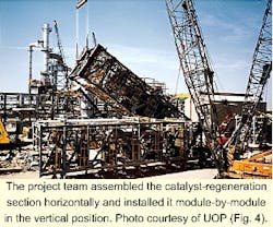
When the module was in a vertical position, the workers removed the lower lifting assembly, and the lead crane lifted the module to the top of the foundation or to the already installed lower module (Fig. 4).
Since the entire CCR section had been horizontally constructed in one single piece prior to disassembly for shipping, the maintenance team found very minimal fit-up problems. Only limited adjustments by shimming were necessary to align the modules in the vertical erected position.
A small number of ship-loose items had been fabricated with provisions for field adjustment, such as the catalyst-transfer lines between the reactor and CCR sections. Safety checks, conscientiously carried out on temporary supports and loose objects at module assembly site, resulted in no incidents during the entire journey to Jamnagar site as well as during the lifting operation.
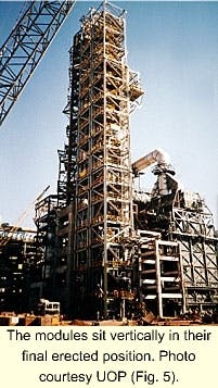
Fig. 5 shows all seven modules in their erected vertical position.
As a result of good design and planning, stacking up all seven modules to a height of 85 m took only 2 working weeks. Installation of all ship-loose items took 7 additional working weeks. Ship-loose items included grating panels bridging the two towers, pipe segments at module breaks, home-run electrical and instrument cables, light tubes, motors, and delicate instruments.
Acknowledgments
The authors thank the project teams of RIL, Bechtel, UOP, and L&T for their teamwork, which made the modular approach for the world's largest Cyclemax CCR section a success. The authors also thank A. B. Shah, RIL project manager, for his active participation in the project execution and Youg Ganju, business executive at UOP, New Delhi, for his tireless effort in working with RIL and Bechtel.
The Authors
Mantri Ganapati is group senior vice-president of the aromatics group at Reliance in Jamnagar, Gujarat, India. He has been closely associated with Reliance's aromatics business since 1985. He has 30 years of experience in health, safety, and environmental; project engineering; and process engineering groups. Ganapati holds a BSc and MTech in chemical engineering from Andhra University, Visakhapatnam, Andrhra Pradesh, India. He also did post-graduate work in chemical engineering at the same university.
Richard Ding is a senior project manager of the modular plants and systems division at UOP LLC in Des Plaines, Ill. With the exception of 2 years with Brown & Root International, he has worked for UOP for his entire career. Initially, he worked at Procon International, a subsidiary of UOP, as a design engineer. He later worked as project engineer and project manager. Ding holds a BS in civil engineering from National Taiwan University and an MS in civil engineering from St. Louis University. He is also a registered professional engineer in Illinois.
P.D. Mooley is an assistant general manager in the chemical plants and systems business unit at Larson & Toubro Ltd., Mumbai. He has 21 years of experience in EPC in the petrochemical and refining industries. He began his career with National Organic Chemicals Ltd., a petrochemical company near Mumbai. He has since worked for major companies such as Yanbu Petromin refinery, Saudi Arabia, Reliance Industries, Mumbai, and Finolex Industries Ltd., Pune, India, before joining L&T. Mooley holds a bachelors degree in mechanical engineering from the College of Engineering, Pune, and a masters degree in mechanical engineering from the Indian Institute of Technology, Mumbai. He also holds a diploma in management from the Institute of Management Development & Research, Pune.
