Study examines use of refinery fuel gas for hydrogen production
Refiners faced with increasing hydrogen demand should consider producing additional hydrogen from fuel-gas streams.
The use of refinery fuel gas, excess LPG, butanes, and pentanes for hydrogen production is a logical fit for refineries. Refinery fuel-gas flow and composition variations can be frequent and sudden. Our experience is that this flexibility can be built into a hydrogen plant.
Difficulties with these designs include:
- Properly removing liquids and solids from refinery fuel gas upstream of compression.
- Compression of gas with varying molecular weights.
- Protecting the steam-methane reformer from undesirable components.
- Providing controls for continuously operating the plant at peak efficiency.
Special design provisions must be made to maintain a constant quantity of coproduct steam from the hydrogen.
This article discusses the difficulties in designing and operating hydrogen plants using multiple feeds.
Hydrogen demand
Refiners are experiencing increasing pressure to produce cleaner fuels while processing more sour and heavier crudes. The need to meet clean-fuel specifications requires additional investment in hydrotreating capacity. The use of residue-upgrading technologies, such as hydrocracking and coking, also increases hydrogen demand.
These technologies also create additional volumes of refinery fuel gas that must be used within the plant. Some refineries already have a very tight fuel balance, occasionally limiting crude processing.
The use of refinery fuel gas to make hydrogen is a logical solution. In the past, refinery fuel gas came from one or two sources such as a hydrotreater purge or catalytic reformer gas; today it comes from many sources, which increases hydrogen plant complexity and operation.
Refinery gas sources
Refinery fuel gas is a mixture of streams generated in various refinery operations such as hydrotreating, hydrocracking, catalytic reforming, catalytic cracking, coking, etc. Today’s refineries are built to accept varying qualities of crudes, such as heavy or light and sweet or sour. They may also operate differently during summer and winter months to meet different product slates. Unit start-ups or shutdowns add to this complexity.
Fuel gas is generally used as fuel in various process heaters and steam boilers in the refinery, but using it as a feedstock for hydrogen plants presents operators with real obstacles.
Normally, a refinery has two different fuel systems-one that collects gases with mainly saturated hydrocarbons, and the other that collects streams with significant unsaturated hydrocarbons. Saturated hydrocarbon streams originate from operations such as hydrotreating, hydrocracking, and catalytic reforming. Unsaturated streams originate from catalytic cracking, cokers, etc.
Refineries have little need to analyze refinery streams being sent to fuel because fully characterizing them is a tedious laboratory process. Whenever refiners do analyze these streams, they generally limit the analysis to pentane or hexane components.
Heavy components (up to C12) may be present in concentrations less than 1,000 ppm; these heavier components reduce a stream’s dewpoint and occasionally cause condensation. Based on the source of the fuel gas, it is prudent to account for heavy components during the design of hydrogen plant.
Because fuel-gas composition can change without notice, continuous composition monitoring is desirable. Monitoring can use gas chromatography, mass spectrometry, density meters, heating-value measurement, or dewpoint measurement.
The analysis is used for process control and protection of the hydrogen plant from unwanted components. Each of these analyzers has its limitation in terms of speed of analysis, accuracy, and reliability. It is important to match the process requirements with instrument capabilities.
Liquid, particulate removal
It is also important to remove condensed liquids and any solids from fuel-gas streams. Many streams are at their hydrocarbon dewpoint when leaving the final separator of their respective source.
Some of the streams may become saturated with water when processed in an amine treater. Liquid entrainment from the separator and condensation in the fuel-gas header results in significant amounts of liquid present in the fuel gas.
Safety concerns also arise if the fuel gases are used in furnaces in cold climates. Condensate will be a sour mixture of water and hydrocarbons. Proper removal and disposal of this condensate is an important consideration for plant operations.
Refinery fuel gas may also contain solids from their original sources or picked up from the fuel header. Removing these solids is important for safe, trouble-free operation of compression equipment or processing equipment such as burners and catalytic reactors handling the fuel gas. A coalescing filter for solid removal is desirable.
Reformer design for fuel gas
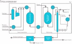
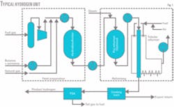
Fig. 1 shows a typical hydrogen plant using refinery gases and liquid hydrocarbons.
The feed-preparation section consists of gas compression and vaporization of the liquid feeds such as LPG, butanes, and pentanes. The hydrocarbon feed is desulfurized, mixed with steam, and sent for reforming.
The reforming section usually has a tubular reformer and may also have an adiabatic pre-reformer. A pre-reformer may be needed if a significant amount of heavy hydrocarbons such as pentanes are to be processed. It is critical to desulfurize the hydrocarbon feed properly because the pre-reformer and tubular reformer use nickel catalysts that are very sensitive to sulfur poisoning.
Reformed gases are cooled and sent to a shift reactor to convert carbon monoxide to hydrogen and carbon dioxide. The shifted gas is cooled and processed in a pressure swing adsorption (PSA) unit, which recovers 85-90% of the incoming hydrogen.
The rest of the hydrogen, unconverted methane, carbon monoxide, and carbon dioxide removed in the PSA are used as fuel in the tubular reformer.
Compression of fuel gas
Refinery fuel gas is normally available at 60-200 psig. It usually needs to be compressed to 400-600 psig to feed a steam-methane reformer. There are many compressors that can be used in this service, including centrifugal, reciprocating, and screws (oil-flooded as well as dry).
A centrifugal compressor may be a good choice from cost and ease of maintenance points of view, but the molecular weight of the gas being compressed greatly influences its performance. One should carefully evaluate the variability in fuel-gas composition to assess the suitability of such a machine.
A reciprocating compressor is more flexible; it can accept varying compositions in its feed. The gas composition affects the compressor discharge temperature for a given compression ratio. Because the specific heat of hydrogen is lower than that of hydrocarbons, a higher hydrogen content results in a higher discharge temperature. The temperature of the compressor valves is also affected by higher hydrogen content. A conservative design may require limiting compression ratio of each stage.
An oil-flooded screw can provide high compression ratios (6-8) in a single-stage machine, but the compression efficiency for these machines is significantly lower than reciprocating or centrifugal machines. Any condensation of water or hydrocarbons in the compressor contaminates its oil and, although these machines should be designed to avoid this, an upset at the refinery can bring in heavy components that could condense at the compressor’s discharge conditions.
It is important to make a proper selection of the compressor based on operating experience, cost, and reliability requirements.
Hydrodesulfurization design
Refinery fuel gas generally contains much more sulfur than a typical natural gas feedstock. Sulfur species in fuel gas such as carbonyl sulfide and heavier mercaptans are also harder to remove or hydrotreat.
In the first step in a hydrotreater, all organic sulfur species are hydrotreated to convert them to hydrogen sulfide. In the second step, a zinc oxide bed removes the hydrogen sulfide. Commonly used hydrotreating catalysts such as nickel molybdenum or cobalt molybdenum must be properly sulfided to be fully active.
Hydrogen must be present to convert various organic sulfur compounds to hydrogen sulfide. The amount of hydrogen in the refinery gas varies, but should be sufficient for this process.
If a feedstock with low sulfur, such as natural gas, is processed in the hydrotreating unit for any length of time, it tends to remove sulfur from the hydrotreating catalyst. Hydrogen in the feedstock should be a minimum to prevent it from stripping the sulfur off of the hydrotreating catalyst during such an operation.
Metals on the catalysts are reduced to free metals and become active for hydrocracking reactions. If these reactions are initiated, the resulting temperature runaway could be severe. Hydrotreating catalysts can be resulfided, if necessary, by addition of sulfur compounds such as dimethyl disulfide.
The presence of hydrogen in the fuel-gas feed also requires that the hydrotreating and zinc oxide reactors be built of materials suitable for hydrogen partial pressure in the feed gas.
Refinery fuel gas may also contain olefins. Olefin hydrogenation in a hydrotreating unit is exothermic and the maximum operating temperature limit for the catalyst in this reactor is 750° F. Assuming a minimum inlet temperature of 500° F. and a temperature rise of 250° F., a maximum allowable limit of 5% olefins in feed would be acceptable. A recycle loop equipped with a cooler allows the process to handle more olefins in the feed.
The designer must pay special attention to acetylene, if present, in the fuel gas. Acetylene polymerizes on the hydrotreating catalyst. The maximum concentration should be 10 ppm (vol).
Feed measurement, analysis
The steam-to-carbon ratio is a critical parameter that the refinery must control for efficient and safe operation of a steam-methane reformer. The varying fuel-gas composition makes it difficult to obtain an accurate real-time measurement of the flow rate and carbon number of the stream.
A mass flowmeter or a vortex-type meter can accurately measure fuel-gas flow rate. Because the stream is usually at 600-1,000° F., the flowmeter may have temperature limitations.
Real-time measurement of the carbon number is more difficult. A gas chromatograph can continuously monitor the composition of the fuel-gas feed. Gas chromatographs operate with about a 10-min delay, however, and cannot be used for process control.
A mass spectrometer with a fast response time may be suitable. Its initial cost and reliability, however, may make it impractical. An inexpensive and reliable density meter can be used as a measure for the carbon number.
To maximize use of refinery fuel gas, a refiner may use it as makeup fuel in the tubular reformer. Fuel gas used as fuel is usually a different stream from the fuel-gas stream fed to a steam-methane reformer.
Temperature control of the reformer furnace is sensitive to variations in the quality of the makeup fuel. It is important to know the real-time flow rate, heating value, and gas density of the fuel gas to control a furnace properly. A quick-response calorimeter can make a heating-value measurement. The calorific value with a density measurement can be used for firing controls as well as for proper accounting purposes.
It is also important to have continuous H2S and total sulfur analysis of the refinery fuel gas. The hydrogen plant must stay below a sulfur emission value limited by any environmental permit. The refinery must substitute an alternative fuel source, such as natural gas, for fuel gas when it exceeds a specified sulfur content.
Reformer optimization
Operating a steam-methane reformer at peak efficiency requires online optimization, and the variability of the refinery fuel-gas feedstock complicates this activity. An increase in hydrogen content in feed reduces reformer duty, which leads to reduced fuel usage. It also increases unconverted methane leaving the reformer for a given outlet temperature.
The amount of carbon dioxide produced in the reformer per unit of hydrogen production is also reduced. This lessens the amount of steam production in the convection section of the tubular reformer.
The reverse will be true if the amount of heavy components in the feedstock, such as butanes and pentanes, increase.
By-product steam available for export will vary with the quality of the refinery fuel gas. If a constant steam export is desired, the unit must be designed to augment the steam production by other means such as auxiliary firing in the furnace of the tubular reformer.
Case study
An optimization study, done for a hydrogen project for a refinery in North America, illustrates the effect of variations in feedstock on plant performance.
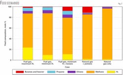
This plant was designed to produce hydrogen with various feedstocks including refinery fuel gas, butane, pentane, and natural gas. Fig. 2 shows some of the feed scenarios that we considered.
Assuming that the plant operates at a constant methane and carbon monoxide conversion, then varying the reformer outlet temperature and the shift inlet temperature can compensate for the effect of feed changes on the chemical equilibriums in the reformer and shift converter. Table 1 shows these effects.
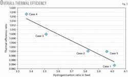
These variations affect the overall process thermal efficiency (Fig. 3). Inherently, thermal efficiency falls as the feedstock becomes heavier, as reflected in a lower hydrogen-to-carbon ratio. The effect on efficiency is more pronounced if the operating conditions, such as reformer outlet temperature or shift temperature, are not adjusted for the feed composition.
As the feed quality varies, steam production and available export quantities will vary even at constant hydrogen production. Adjusting the temperature of combustion air for the tubular reformer furnace or auxiliary firing in the furnace will minimize variations in steam exports.
Additional measurements and controls in the convection section and PSA are also required for plant optimization.
The authors
Bhadra Grover ([email protected]) is a group senior expert for Air Liquide, Houston. He has also served as process manager at M.W. Kellogg (now KBR), and Union Carbide Corp. (now UOP LLC). Grover holds a BTech (1967) in chemical engineering from the Indian Institue of Technology, New Delhi, and an MS (1978) in chemical engineering from Manhattan College, New York. He is a member of AIChE.
Pietro Di Zanno is a group senior expert and global marketing manager (oil and gas market) for Air Liquide SA, Paris. He has also served as business development manager for Air Liquide Canada and as a process specialist, lubes and bitumen upgrading, for Shell Canada Products. Di Zanno holds a Bachelor of Engineering-Chemical (1985) and an MBA (1992) from McGill University, Montreal.


