Innovations drive pipeline installation in Cook Inlet
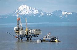
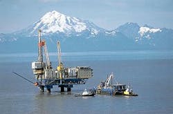
In summer 2002, three pipelines were installed by the pull method to Forest Oil Corp.'s Redoubt Shoal field Osprey platform, Cook Inlet, Alas., in a project that used new technology in several areas.
The line pipe consisted entirely of heavy-wall seamless tubulars designed to remain stable in tidal currents up to 13 fps. The pipe was coated with three-layer polypropylene for abrasion resistance and reduction of friction factor.
null
The three pipeline shore approaches each consisted of 12.75-in. OD x 1,800-ft long drilled approaches that were initiated from a bluff 200 ft above Cook Inlet. Two different drilling and casing techniques were used.
The pipelines, up to 8.625 in. OD, were pulled into the platform through 19.5 ft (radius) pull tubes completely contained within the 14-ft diameter platform legs. The pull loads were highest on pipeline entry into the pull-tubes. A simple chain jack, designed and fabricated for the project, exerted pull loads greater than 270,000 lb to pull in the risers successfully.
Finally, the risers and pipelines were installed with simultaneous application of tension from the platform-based chain jack on the pipe end and a barge-deployed pull wire engaged 500 ft down line.
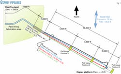
Fig. 1 shows the offshore reaches of the Osprey pipelines. The Osprey platform lies about 2 miles from the 200-ft high bluff that was crossed by directional drilling.
The pipelines were designed to meet the requirements of US 49CFR192 Transportation of Natural and Other Gas by Pipeline: Minimum Federal Safety Standards, and 49CFR195 Transportation of Hazardous Liquids by Pipeline.
All offshore pipe was seamless quenched and tempered material.
Pressure design
The offshore portion of the pipeline system consists of three parallel pipes:
- 8.625 in. OD x 0.750 in. WT X-52 to convey produced fluid (a mixture of oil, water, and dissolved gas) from the Osprey platform to the Kustatan onshore processing facility. Maximum allowable operating pressure (MAOP) is 3,705 psig with a corrosion allowance, considering pressure only, of 0.323 in. for the pipeline and 0.238 in. for the riser.
- 8.625 in. OD x 0.875 in. WT X-60 for return of injection water from the Kustatan processing facility to the platform under high pressure. MAOP is 5,000-psig with a corrosion allowance, considering pressure only, of 0.376 in. for the pipeline and 0.276 in. for the riser.
- 6.625 in. OD x 0.750 in. WT X-52 spare line suitable for gas, hydrocarbon liquid, or injection water transportation. The design MAOP is 5,000 psig in liquid service, 4,177 psig in gas service.
Considering pressure only in gas service, there is a corrosion allowance of 0.308 in. for the pipeline and 0.113 in. for the riser.
The derated pressure for gas service arose from the requirement of 49CFR192.619 to hydrotest the riser to 150% of MAOP compared with the 125% of MAOP test specified by 49CFR195 for liquid service.
Stability
The pipelines were designed for a maximum tidal current of 13 fps at the surface of the Inlet. The tidal current was assumed to run 90° to the pipeline alignments. The maximum tide is 30.2 ft.
The maximum current occurs midway through the ebb tidal cycle when the actual water depth at any particular point is the minimum low low water depth plus 15.1 ft of tide. Ebb tide current dominates as numerous rivers and streams drain into Cook Inlet yielding a net outflow.
In addition to the current, the stability calculations assumed simultaneous occurrence of 10 ft significant height wave with a period of 7.5 sec. The angle of incidence of the waves to the pipeline route was a conservative 90°.
Stability was also checked for a 100-year return wave with a maximum height of 28 ft and a period of 8.5 sec.
The required WT for stability was calculated with two independent means.
The first method used the computer program developed by the American Gas Association.
Only the AGA Level 1 analysis was applied because the AGA Level 2 analysis incorporates self-burial effects not applicable in the environment of Cook Inlet.
The second method used a spreadsheet with embedded macros to perform the calculations described in DNV RP E305 On-Bottom Stability Design of Submarine Pipelines.
The submerged weight for stability was developed solely by increasing the thickness of steel pipe wall and not by concrete weight coating. Although more costly, adding weight by steel is efficient because weight can be added with no change in the OD of the pipe.
Each pipeline was installed by pulling through a 12.75-in. OD x 0.408-in. WT drilled and cased shore approach.
If concrete weight coating had been used, the diameter of the casing would have had to be increased at considerable extra expense. Finally, the pipeline pull loads were kept low by using low-friction-factor polypropylene coating rather than concrete.
Vortex-induced vibration
Another type of loading that can result from swift currents is vortex-induced vibration or "strumming." For this phenomenon to occur, some length of pipe must be suspended in the seaway and free to oscillate.
The pipelines were analyzed using a spreadsheet with embedded macros to perform the calculations described in Section 7 of DNV CN30.5 Environmental Conditions and Environmental Loads.
The calculations determine the maximum allowable unsupported length before a pipe becomes vulnerable to oscillation and fatigue damage.
The calculated maximum span lengths for the Osprey lines ranged from 34 ft for the 6.625-in. pipeline to 43 ft for the 8.625-in. pipelines. Cook Inlet, however, has seen a number of vortex-induced vibration pipeline failures, and experience has shown that for an 8.625-in. OD pipe failed spans are invariably longer than 100 ft.
With due regard for theory and experience, the maximum allowable span was set at 50 ft.
Pipe coating
The installation method required the pipe to drag on the ground in the 4,600-ft long fabrication area, pass through a 1,800-ft long steel conduit to make the transition from land to sea, cross 10,700-ft of rocky seafloor, and finally board the platform via a 12.75-in. pull-tube with a 234.5-in. radius bend.
It was essential that a tough coating be applied to survive this installation regime. The coating selected was plant-applied three layer polypropylene (TLPP).
TLPP consists of a layer of fusion bonded epoxy (FBE) on grit-blasted pipe, followed by a thin copolymer adhesive layer and a wrapping of polypropylene (PP) film.
The FBE is the corrosion barrier, with the tough PP jacket ensuring it is in place when installation is complete. The copolymer is actually a blend of finely ground FBE and PP. The bond is formed by mechanical interlock of the gelled FBE and the PP particles that in turn bond to the PP wrap.
The PP wrap is side-extruded whereby hot plastic is wrapped on the pipe in a multilayer spiral.
The grain of the coating wraps around the pipe and is well oriented to resist splitting. The PP layer is bonded to the pipe at all points, so that even if the PP is slit in the course of installation, the jacket will not ravel or peel off.
Normal thickness for TLPP coating is about 80 mils. For the Osprey project, a thickness of 150 mils was applied to the offshore pipe. This thickness proved adequate because two of the three risers were electrically insulated from the platform structure upon completion of the riser installation sequence.
These pipes were electrically bonded to the structure immediately after installation to ensure the pipes would not be galvanically sacrificed in the impressed current field that protected the platform from corrosion.
The girth-weld field joints were sand blasted and coated with two-part epoxy primer. This was in turn coated with PP shrink sleeves. To optimize pipe temperature for cure of the shrink sleeves, every epoxy-primed girth weld was precisely heated by electrical heat induction.
Pull-tube risers
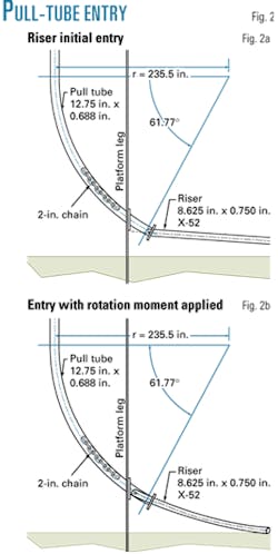
The legs of the Osprey platform are 14 ft diameter columns and subject to ice loads. The pull tubes are totally contained within the leg structure. The tubes have a bend radius of only 234.5-in. and the tubes terminate with a downward orientation after 61.77° of bend.
In every instance, the highest pull-tube loads occurred during entry of the pipeline into the tube. Fig. 2a shows the geometry at entry. From this initial position, the end of the pipe had to rotate up to continue into the tube (Fig. 2b).
Because the bottom of the tube was close to the seafloor, the pipe actually had to yield in bending to make the entry. The moment arm between the pulling shackle pin and the fulcrum where the pipe contacted the mouth of the tube is relatively short. Therefore a large tensile load was required to induce a plastic moment at the pipe fulcrum point. An analytical formula for ultimate moment1 follows:
My = 1/6 Y (D3-Di3)
D = pipe OD
Di = pipe ID
Y = Yield stress
For 8.625 in. x 0.750-in. WT X-52 oil line riser;
D = 8.625 in.
Di = 6.875 in.
Y = 52 ksi
My = 2,740-kip-in.
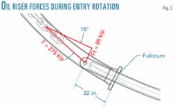
A moment arm of L = 32 in. is shown in Fig. 5. The force perpendicular to the pipe axis (Fp) is:
Fp = My/L
Fp = 2,740 kip-in. /32 in.
Fp = 85 kip
The corresponding tensile pull-in load is described by the force vectors shown in Fig. 3. The force by graphical solution is F = 275 kip.
This compares to an actual observed force of 270 kip during pull-in of the oil riser.
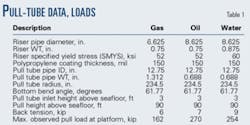
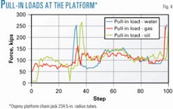
Table 1 shows the actual forces observed during riser pull-in. Fig. 4 shows the loads for the complete pull sequences.
Other data that supports this explanation for the pull tube forces are:
- The maximum force in every instance arose and then dissipated after a single pull stroke (16 in.).
- The force invariably arose when the riser was entering the pull tube.
- The riser pipe after pull-in had a plainly visible residual plastic bend about 30 in. back from the pull-head.
The maximum riser-pull loads were caused by force couples needed to bend the riser for entry into the tubes. The maximum pull-in force greatly depends on the pipe geometry at or near the point of plastic bending. An onshore test may well be in order for pull-tubes with similarly steep or otherwise difficult entries.
Chain jack
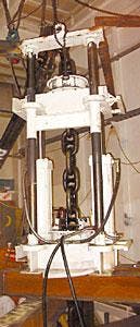
To apply the riser pull-in loads, a 2-in. x 120-ft long stud link chain was connected to the end of the riser. The chain was drawn up by an intermittent-operation chain jack specifically designed and fabricated for the project (Fig. 5). There were several reasons for this:
- The risers were located in two different leg rooms with entry via ordinary 3-ft wide doorways. Any system had to be small, lightweight, and readily relocated.
- The pull-in loads were relatively high due to the tight radii of the pull tubes and the heavy pipe walls of the risers. Chain was judged the most easily handled tensile element adequate for the pull.
- Because the pulls were relatively short, speed and continuity of operation were not a concern.
- Drilling operations were ongoing at the time of pipeline installation. It was desirable to have a compact system located away from the drilling operations.
- The alternative, a linear winch system, was considerably more costly.
- No existing chain jacks of the requisite size were available for hire or purchase.
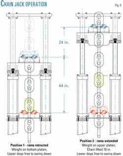
A chain jack functions by pulling chain in a hand-over-hand manner (Fig. 6) There are two positions, rams extended and rams retracted.
When the rams retract, the chain is engaged in the lower support platen; with the rams extended, the chain is engaged in the upper support platen. The simple jack built for Osprey required the unloaded upper chain be kept tensioned with an air tugger line.
The key component of the chain jack is the platen and dog assembly that secures each knuckle of the chain for pulling.
The Osprey chain jack had 4-in. thick x 16-in. diameter round platens with 1-in. deep pockets for the dogs.
During normal operation, the dogs were held closed by elastic tied between the operating handles. Utilizing a ratchet principle, upward movement of the chain automatically swung the dogs aside for chain passage.
After a chain knuckle cleared the dogs, they would snap back to the down position and thereby be ready to engage the chain for holding (the lower platen) or the power stroke (the upper platen).
The platens were round to permit rotation of the chain without rotating the entire device. The chain had a pitch of 16 in. for each stroke.
The rams stroked 24 in. The over-pull was required to give the dogs clearance to snap back for chain engagement.
The only machining on the device was the 1-in. deep dog pocket and the relief for the chain in the dog.
This produced a very close fit. To keep costs low, all other components were fabricated by precision flame cutting. The 7-in. diameter x 24-in. stroke rams were standard off-the-shelf hydraulic components.
A 20-hp electric-motor-driven power supply provided fluid power to the jack. The only hydraulic control was a standard four-way spool valve to control ram extension and retraction. When reverse operation was needed to slack the chain, the dogs were operated manually.
Drilled shore approaches
Each pipeline and the submarine power cable were provided with a separate 1,800-ft long drilled shore approach. The initial 600 ft of each boring was cased with 20-in. pipe for two reasons:
1. The shallow soils were known to have a scattering of boulders that could divert a smaller conduit if hit the wrong way.
2. The casing kept the hole from collapsing after the drill emerged at the seafloor and the drilling fluid equalized with the sea.
The complete drilled approaches were fully cased with 12.75-in. OD x 0.408-in. WT steel casing. Casing joints were joined by welding.
Two installation methods were employed:
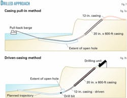
1. The method planned for the project was for the complete welded casing to be installed by pulling it through the partially cased and partially open hole from offshore.
The sequence was as follows:
- The 20-in. x 600-ft long casing was driven to below sea level.
- The hole was drilled out to the exit location at .22 ft elevation.
- A cable from the barge was attached to the drill string by divers and pulled back to the top of the bluff.
- A prefabricated casing string was then connected to the cable and pulled back toward the barge.
This method was made to work in two instances, but there was trouble with the barge cable getting stuck in the open hole and with the casing failing to make the full distance (Fig. 7a).
2. The second method developed was to install the casing by alternating drilling forward and driving casing. This kept the hole cased just behind the advancing drill.
- Again the first step was to drive the 20-in. x 600-ft long surface casing. For the balance of the hole the drill bit was closely followed by casing installed one joint at a time in an overshot of the drill string (Fig. 7b).
- The casing was driven by a 24-in. diameter x 12-ft long, 10,580-lb, 180-blow/min pipe ramming tool. This unit was powered by compressed air.
The driven casing method was somewhat more time consuming than a perfectly executed casing pull-in, but as mentioned previously the pull-ins suffered numerous delays and risky stuck-pipe situations.
The driven casing method also had the advantage of not requiring any pull barge support. The clarity of 20-20 hindsight reveals that the barge should not have been mobilized until the casings were complete.
Pull barge installation
The pipelines were installed by pulling the completed pipes offshore using a winch mounted on a barge.
The barge was moored in three positions (Fig. 1).
All three pipes were pulled as close as practical to the first two locations before the barge moved back and re-moored for another sequence.
When the end of the pipe was 200 ft from the mouth of the pull-tube (close enough to be pulled to the platform), the barge pull wire was re-rigged to a pulling collar located 500 ft from the end of the pipe.
This collar was a solid forged spool of ASTM A707 material with a machined shoulder.
To bring the end of the pipeline to the mouth of the pull-tube, a 1-in. messenger wire was run down through the pull-tube. The wire then went from the mouth of the riser to the end of the 2-in. x 120-ft long stud link riser pull-in chain.
Then, with simultaneous pulling from the barge and the platform, the end of the pipeline was brought to the pull-tube entry.
This arrangement was designed to minimize pipe lateral excursion over the rocky seafloor.
Upon completion of bringing the pipe to the pull-tube entry, the end of pull-in chain was at the deck of the platform. The chain could then be engaged in the chain jack for the final pull.
The final pull was made with the chain jack and the pull barge alternately pulling about 10 ft of pipe for each step. Pipe movement was monitored at the beach for the barge pull sequences and by counting chain links for the platform sequences.
To ensure straight and smooth pipe entry into the pull-tube, the shape of the incoming riser pipe was monitored by scanning sonar.
Barge design, pull loads
The barge used for pulling was flat bottom, 76 ft wide x 300 ft long. It was moored with four each 1-3/4 in. mooring wires terminated with 30,000-lb Danforth anchors. The barge was moored in line with the tidal currents to minimize current forces on the mooring system.
The pipelines were pulled with a single parted 2-in. wire rope. A further two 13/4-in. mooring wires terminated with 30,000-lb Danforth anchors were used as hold back anchors for the pipeline pulls.
The barge was supported throughout the project by two tugs. A 100-ton crawler crane was on deck. The barge sailed with a comprehensive spread of equipment and supplies including a spare anchor, spare mooring wire, and spare pull wire.
Barge positioning was by differential global positioning system. The anchor running tug position was continuously available by data link at the survey desk on the barge.
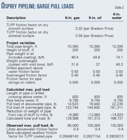
Table 2 shows calculation of the pull loads for the three pipelines. The principal unknown was the friction factor for the TLPP coated pipe on the seafloor. A friction factor of 0.40 was used for the calculations.
Back calculating the friction factor based on maximum observed pulling forces showed a remarkably consistent actual friction factor of slightly more than 0.28 for all three pulls.
Pipeline fabrication
The three pipelines were each welded into three strings for a total of nine strings; Fig. 1 shows the 4,600-ft long pipeline-fabrication area.
This area followed the onshore pipe route to the processing facilities, and the fabrication alignment therefore contained two curves. For the first couple of pulls, Vee-rollers were installed at key locations, but it was difficult to keep the pipe on them, and when the pipe fell off there was often coating damage caused by the steel structure of the roller box. It was found the pipe was best left on the ground and helped along with side boom tractors.
At the bend locations track hoes with suspended roller boxes were positioned to keep the pipe from sliding laterally. When the pipes were fed into the drilled approaches during pulling, the overbend was controlled by a high roller box.
Submerged manual arc welding with gamma-ray radiographic inspection was used for all welds. All line pipe, flanges, and spools were joined with full-penetration butt welds (i.e., no fillet welds were detailed in the onshore or offshore rights-of-way).
All girth-weld field joints were sand blasted for surface preparation and coated with two-part epoxy primer and tube-type PP shrink sleeves. Shrink sleeves were heated and cured by electrical induction heating of the pipe. There was an interruption in coating operations when the 400-hz induction heating generator failed and a replacement had to be brought by truck from Houston.
Acknowledgments
The authors acknowledge permission from Forest Oil Corp. to publish this material.
Reference
1. Langer, C.G., "Calculation of J-lay Pipe Spans, Analytical Solutions," J-Pipelaying Workshop, in conjunction with ASME ETCE, Feb. 7-8, 2001.
Based on a presentation to the Offshore Technology Conference, May 5-6, 2003, Houston.
The authors
Robert Gilchrist ([email protected]) is chief civil engineer with Cannon Associates, Bakersfield, Calif. He is retired from Shell Oil Co. and owned a consulting practice for several years. He holds a BS in chemistry from Colorado State University and an MS in civil engineering from the University of Wyoming. Gilchrist is a registered professional engineer in Colorado and Texas.
Robert C. Visser ([email protected]) is a private consultant for Belmar Engineering, Redondo Beach, Calif., with more than 40 years of offshore field development experience. Before forming Belmar, he was with Shell Oil Co. for 29 years. Visser holds an MS in civil engineering from Delft Technology University in the Netherlands.
Gary E. Carlson retired from Forest Oil Corp., Denver, earlier this year, his most recent position there being senior vice-president for the company's Alaska unit (OGJ, Dec. 9, 2002, p. 24). He was vice-president for Forcenergy Inc. from 1997 until its merger with Forest Oil in 2000, and he worked for Unocal Corp. for 28 years. Carlson holds BS and MS degrees in petroleum engineering from Montana Tech of the University of Montana, Butte, Mont.
