Flexible manufacturing provides just-in-time, custom-made drill bits
Flexible manufacturing facilities, enabled by computer-assisted drafting and manufacturing (CAD, CAM) technologies, can now deliver custom-designed polycrystalline diamond compact (PDC) bits within 4-5 days, allowing operators to improve drilling performance in successive well activities.
And with bit costs affecting only 5% of a well's drilling investment but drill-bit performance affecting 80% of a well's costs, the possibility of just-in-time delivery may revolutionize the relationship between oil field operations and the factory (see box).
"We've developed a work process with log and seismic data where we characterize the formation, along with the drilling data, to build a better bit," said Bill Calhoun, senior drilling engineer for Chevron Petroleum Technology Co. "But what really sets us apart is the ability to get very accurate data in the hands of the bit people in a timely manner."
This system of geologic and engineering analysis, supported by cross-functional teams involving drill-bit design engineers, drilling engineers, geologists, petrophysicists, geophysicists, and manufacturing personnel, has aided Chevron with many of its endeavors around the world including West Africa and Hibernia.
"As we are completing the current well, we are already analyzing the data and designing a new bit for the next one," Calhoun said, "and this process can be continued well after well."
Although it's not a standard course of business, said Van Perrin, drilling engineer advisor for Chevron, when they "come up with ideas to cut faster hole, engineers can also take an existing design, mid-stream in the design-and-manufacturing process, and produce an improved PDC bit."
Eventually, cycle times may be reduced to the point where bits can be re-engineered, manufactured, and delivered to a wellsite on the same well, providing operators with a means to handle abruptly changing geologic environments as new information becomes available.
This first of a two-part series describes the interacting relationships between CAD, CAM, and PDC drill-bit design activities, provided within the context of systems development. The conclusion provides an exclusive look into the flexible manufacturing process itself.
Flexible manufacturing
The oil industry is not the first to implement flexible manufacturing systems, with Japanese automobile makers spearheading such developments in the 1970s. Today, flexible manufacturing processes have spread into many facets of everyday life with companies like Levi Strauss Co. producing tailor-made, skin-tight jeans from measurements taken at the point of sale.
Yet for Hughes Christensen, the change came about in 1986 when the company began to use numeric-controlled milling equipment with CAD software. "The most significant change in our industry is the automation of the design-and-manufacturing processes," said Roland Illerhaus, product manager of diamond drilling tools for Hughes Christensen.
"It used to be that everything in the manufacturing process was done by hand with manual equipment," he said. Nevertheless, over the last 10 years, the whole industry has made significant efforts to use CAD tools by adding direct data links to the shop floor.
CAD
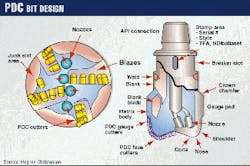
"CAD is used in every step of the design phase," said Roger Lee, drill-bit engineer for Hughes Christensen. When engineers design a drill bit, the CAD system automatically lays out the cutters, fluid nozzles, blades, and junk slots (Fig. 1).
Then, once the design is in place, the CAD file, stored on a network, becomes available to the shop floor where numerical coordinates provide instructions for the turning and milling operations.
The designer works with the CAD program in either 2D or 3D, mostly looking at the bit from two perspectives, top and side views. The program used by Hughes, developed on MicroStation (Bently Systems Inc.) software and operated in a workstation environment, contains layer upon layer of detail.
"The reason we picked our CAD program is because we can manipulate the program," he said, allowing in-house programmers to write additional code. Over the past 2 years alone, Lee said CAD systems have improved Hughes's ability to make changes fivefold.
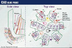
Fig. 2 shows an example CAD "blue print" in which on the right-hand side (Top view), cutters are shown in red and blue while fluid nozzles are represented by circles with arrows. On the left-hand side (Side view), each of the cutters, as indicated by colored circles, correlates with the entire cutter assembly revolved on top of each other, encompassing all seven blades.
In tandem, these two views provide the engineer with the ability to model symmetry and visualize gaps and interactive attributes between the cutters and other bit components (Fig. 3). And because all the PDC components are provided in layers, the engineer can isolate and analyze relationships between nozzles, blades, cutters, and junk-slot depth.
For example, a designer can eliminate all the cutters for Blades 3-7 then analyze fluid cleaning relationships between the nozzle flow and cutters on blades 1 and 2 (Fig. 2).
Design focus
Essentially, "Bit designers focus on improving the stability, aggressiveness, and durability of the drill bits," Lee said. "We have found a strong correlation between these factors."
For example, "If you want a bit that is extremely aggressive, you might have to give up a little bit on stability." However, "If you have a bit that is stable, chances are that it will be durable as well."
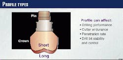
The profile, or blade curvature, directly affects these functions (Fig. 4). "If the profile is long, chances are it will have a hard time staying in balance when on bottom and drilling," Lee said.
For example, "Take a pen with a sharp point on one end and a flat cap holder on the other. The sharp end (long profile), when standing up, will fall down very easily. Thus, it becomes very unstable." On the other hand, the flattened cap end (short profile) has no trouble standing up.
"Unfortunately, you cannot place as many cutters on the short profile as the long," Lee said, "so you must make compromises in the design to produce the optimal bit."
There are many philosophies in the industry as to what size cutters should be used for a particular formation. "Our belief is that for more abrasive, harder formations, you should use larger cutters because they wear slower. If they have more durability, they will last longer," Lee added. "And if there are more blades, you can place more cutters on the bit, allowing us to drill even harder formations."
Experience, modeling, and common sense play a large role in drill-bit design. "From what we have learned, we can extrapolate. We can say that this new high-rpm application will turn a lot so you will probably end up with the gauge pads enduring wear." Thus, the designer will incorporate harder material on the gauge pad.
However, because it is a high-rpm bit, the cutters on the outside will wear at a faster rate as well. "So you may want more durable cutters on the outside also," Lee said. "Essentially, you can take the problem and break it into little pieces, approaching each problem with a solution."
On the other hand, the fundamental principles behind bit design continue to focus on the qualitative aspects, varying from engineer to engineer and company to company.
"The industry has done a lot of learning about tendencies, for example what drills good in shale and what doesn't. But we need to sit down and put numbers on how the bit will perform and how the formations will behave in a quantitative manner," Illerhaus said
Antiwhirl
The use of CAD, especially in directional PDC-bit design, has played an important role in tackling problems associated with whirl, a phenomenon recognized by Amoco 10 years ago in which the drill bit tends to spiral freely around the bit axis (Fig. 5). According to Lee, bit whirl, thought to affect wellbore rugosity, penetration rates, and bit longevity, can be controlled by stabilizing, or holding the drill bit up against the side of the hole.
Whereas tungsten-carbide and steel-tooth bits crush and grind the rock, weight on bit (WOB) causes PDC cutters to indent the formation while rotation (torque) causes the cutters to shear the formation. Thus, each cutter is exposed to a specific torque and WOB force.
The combination of these two dynamic forces, which depend mainly on the location of the cutter, result in a net force of imbalance (Fig. 6). "Traditionally, the objective of a new bit design is to keep the imbalance force as low as possible," Lee said. Thus, to maintain stability, the bit must remain stable along the centerline.
To do this, designers adjust cutter orientation and back rakes, maintaining a low imbalance to make sure it drills on the centerline. With an antiwhirl bit, however, it is just the opposite.
"You actually want the bit to be imbalanced, and through tweaking we are able to control where that imbalance of force is applied," he said. In this case, the bit design embeds an imbalance against one of the gauges pads.
"So essentially what you are doing is placing one of these gauge pads in constant contact with the borehole, where one side of the bit constantly cuts and the other side constantly rubs." This creates a stable rotating condition.
Lee said antiwhirl bits work well because this form of directed instability reduces bottomhole vibrations, inducing less strain on directional bottomhole assemblies, so that it becomes easier to steer and control the bit.
Additionally, because lateral vibrations can easily damage PDC cutters, as compared to tricone tungsten-carbide cutters or steel-tooth cutters, reduced vibrations also promote bit longevity.
Systems development
Although CAD provides an important tool for drill-bit design, producing an important link between information gathered in the field and the manufacturing process, engineers have found that drill-bit design forms only one segment of the drilling system. "It is important that a bit company today be actively engaged in looking at drilling systems as a whole rather than just the bit," Illerhaus said.
As such, some companies, organized around business units with specific product lines, have begun to analyze the interacting relationships between drilling fluids, drill bits, and bottomhole assemblies, leading to the development of integrated product design across the corporation.
For example, Hughes Christensen tackles drilling-performance issues from three aspects: as individual components, as a drilling system, and as a manageable application where design-and-application teams apply extensive studies and research to improve the drilling process.
"First we concentrate on providing best cutter technology, best product integrity, and design. Everything that involves the bit," Illerhaus said. For example, the development of polished cutters (Fig. 7), which provide the same coefficient of friction as ice-on-ice, has successfully reduced the specific energy needed to cut a formation.
As a result, however, this single modification has affected the cutting action of the bit, resulting in the production of cuttings that tend to peel off as long shavings (Fig. 8). Thus, engineers had to take a hard look at what effect increased cutter volumes would have on the drilling system as a whole.
"We actively work on whatever the bit is connected to-the drillstring, motors, stabilizers, shock subs, and drilling mud," Illerhaus said. For example, "We learned that the cuttings can be several feet long (Fig. 8). This was something totally new to us and the industry because mostly what you see at the surface are stubby little cuttings."
Yet as these long strings of cuttings begin to amass in the hole, the mud-carrying capacity, which is a function of cutting size, begins to deteriorate, making it harder to suspend and bring the cuttings to the surface.
To deal with the problem, the company developed a drilling fluid to disintegrate the cuttings, but not to the point where they ball up the bit. "The question now is, if the PDC cutters cut large cuttings, how small should we make them?"
Knowledge management
In a more comprehensive approach to drilling system design, the company may use a turnkey method. This involves multidisciplinary, knowledge-management teams that tie information from offset wells, drilling simulators (Fig. 9), research test facilities, and geophysical data with CAD and CAM technologies to design new drill bits and reconfigure bottomhole assemblies.
For example, Burlington Resources Inc. recently drilled a record 2,083-m, 121/4-in. PDC bit run in Algeria's MLC-2 well, located about 350 km from Hassi Messaoud.
"It is the first time in 15 wells, we drilled the entire interval with one bit run," said Lance Robinson, senior drilling engineer for Burlington. "Basically we gave the whole well to Hughes. We provided them with the lithology, bit runs, and offset data, and they did most of the work." And "With a fixed-price bit proposal, we incurred very little risk except to pay for the study."
In the end, the changing concept of drill-bit design, system integration, and information transfer may alter the way drilling operations are conducted in the future.
ALTHOUGH THE MANUFACTURING PROCESS IS OUT OF SIGHT and mind for the driller on the rig floor, developments in new technologies have actually pushed the supply-and-demand chain closer together, altering the decision-making process for bit selection.
Up until the late 1970s, bit selection was for the most part at the discretion of the toolpusher, driller, or company man. Armed with a large stock of steel-tooth or tungsten-carbide roller-cone bits, provided by a number of bit manufacturers, the onsite drilling supervisor could easily experiment with a variety of bits, well after well, until he found the optimum bit for a particular formation.
Then once the well or drilling program was over, the supervisor simply returned the unused bits to the supplier. This system of bit selection not only promoted competition among the bit manufacturers, leading to successive improvements in bearing and crushing structures, but led to the development of benchmarking studies aided by record keeping at the wellsite.
Inventory and obsoleteness
With the introduction of the PDC bit in 1976, however, and substantial market penetration in the 1980s, this mode of bit selection could not be applied toward PDC bits. In effect, issues of factory-to-wellsite inventory relationships and design obsoleteness forced companies to closely examine and define drill-bit selection much earlier in the planning stage.
For example, a 77/8-in. PDC bit may cost $30,000; whereas button and rock bits cost on the order of $6,000 and $4,000, respectively. Thus, the bit manufacturer could not afford to build up inventory at the factory, nor could the operator afford to hold large stocks on the wellsite.
Additionally, the operator simply did not feel comfortable providing the onsite supervisors total freedom to make bit selection, especially with some PDC bits costing up to $120,000.
Yet even these considerations preclude the most important consideration-product life cycle. Rapid advancements in CAD, CAM, and flexible manufacturing technologies have shortened design-and-manufacturing times to the point where operators can now receive just-in-time, custom-designed bits. Thus, a particular PDC drill-bit design can quickly become obsolete, often in the same drilling program or on the next well.
As a result, the days when all the toolpusher had to do was look out his trailer door and select a bit from a line up, may soon be drawing to a close.


