Methodology helps analyze multiphase pumping systems
The number of multiphase pumping installations is increasing, and it is becoming more important that operating companies understand how to analyze these systems.
The methodology presented in this article is a convenient way for organizing an in-depth, fact-specific analysis but is not intended to cover all possible cases.
The methodology emphasizes conditions normally encountered with surface applications, and the examples are based on twin-screw pumps, which currently dominate the multiphase pump market.
Multiphase pumps
Multiphase pumping technology for the oil and gas industry has been in development since the early 1980s. These pumps simplify production operations by boosting full well-stream flows from satellite wells to a central processing facility, without the need for separation followed by gas compression, tank storage, flaring, and liquid pumping.
By the mid-1990s, multiphase pumping had been used on marginal wells offshore and was being applied to onshore locations. During this period, significant commercial installations were initiated to prove the merits of pump designs. Since that time, about 150 pump units from six or seven different pump manufacturers have been installed.
Twin-screw, progressive-cavity, and helico-axial (H-A) are the predominant multiphase-pump types. The H-A is a high-volume flow, centrifugal-style pump that develops pressure dynamically, hence it can be highly sensitive to variations in density, which is a characteristic of a multiphase flow stream.
The twin-screw and progressive-cavity (PC) pumps are positive-displacement pumps, and therefore, develop pressure hydrostatically, reducing their sensitivity to density changes.
The H-A pump has led the way in multiphase applications on subsea wellheads which tend to have lower gas fractions, strong flows, and the density variations are not as severe as those often encountered on land and offshore surface applications.
For surface applications, positive-displacement pumps have greatly outnumbered H-A pumps due to flows with higher gas-to-total flow volumetric fractions (the gas volume fraction or GVF) and associated tendencies for density changes (slugging).
The authors estimate that over 70% of the installed multiphase pumps are twin-screw pumps, about 20% are PC pumps, and the remaining 10% are H-A pumps.
Projects that appear attractive for multiphase boosting are those where it is possible to simplify surface production management problems, lower costs, and increase production. Multiphase boosting can reduce costs by eliminating or reducing field infrastructures and by reducing losses from flaring, venting, etc.
Functionally, multiphase boosting can be defined as a method to increase the pressure of a flowing mixture of gas, oil, and water-flow components without requiring separation into individual phases which thereafter must be individually managed, treated, and transported. Its value is realized when:
- Lower operating pressures can be achieved near the wells.
- Investment in additional flow lines, flares, and tanks can be avoided.
- Processing can be centralized so that heat, controls, chemicals, treatment methods, and technical talent can be focused.
- U.S. Environmental Protection Agency (EPA) compliance issues can be eased by using a "sealed flow" boosting system.
Field applications
Texaco Inc. is one of the foremost users of multiphase pumps. The company has been involved as an active participant in rigorous multiphase-systems testing for its joint industry program (JIP) in 1992 at its well known flow test facility in Humble, Tex. This facility simulates a variety of field conditions with various crudes and flow regimes.
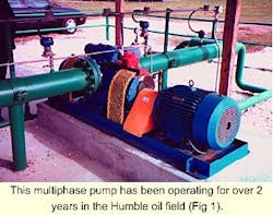
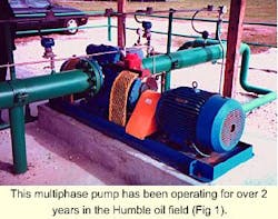
Texaco also has operated pumps in the Gulf of Mexico and Trinidad, and has over 2 years of continuous multiphase pumping experience in the old Humble oil field (Fig. 1). This pump still operates with its original single mechanical seals and demonstrates some of the important operating design principles of multiphase pumping system (Fig. 1).
Chevron USA Inc. has been another leading user of multiphase pumps. During 1993-94, Chevron procured two twin-screw pumps, one for onshore and one for offshore deployment.
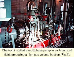
The first pump was commissioned in Alberta for onshore use and is currently operating in a high GVF (96%) service with 23? API gravity waxy oil, water, and gas (Fig. 2). It gathers production from multiple wells to transport the full well stream to a central processing facility, several miles away.
This single pump currently runs at 3,600 rpm and is handling about 3.5 MMcfd gas, 1,800 bo/d, and 11,000 bw/d with inlet pressures near 150 psig and discharge at 500-600 psig.
Using multiphase pumps was the most economical approach for this application when comparing the pump option to a complete separation facility, according to Chevron.
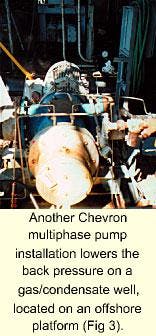
The second pump is located on an offshore platform and is used to lower back pressure on a gas/condensate well from 150 to 30 psi (Fig. 3). This small 75-hp pump handles about 21,000 b/d equivalent of 31? API gravity oil and natural gas from a single well. Chevron was successful in realizing an incremental increase of production averaging 50-150 bo/d, resulting in payout of its costs in a few months.
In late 1998, PT Caltex Pacific Indonesia installed two multiphase pumps at the Duri field in Sumatra for a light-oil, steam-flood project. One is a twin-screw pump and the other is an H-A style pump. The pumps were installed in parallel to compare their resistance to sand abrasion in the presence of intermittent steam.
Both pumps are now in operation and under evaluation.
Petróleos de Venezuela S.A. (Pdvsa) also reported the commercial use of several multiphase pumps on three heavy oil projects and are continuing to evaluate these pumps for other crudes.
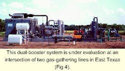
More recently, Ocean Energy Inc., in cooperation with Weatherford Global Compression Services and Flowtronex International, is employing a dual-booster multiphase system. "Dual Booster" is a trademark of Weatherford Global Compression Services L.P. and the system has a patent pending.
This system is under field evaluation as a method to reduce costs and power requirements for multiphase boosting in high gas-fraction flow environments and as a way to reduce emissions at field locations.
This pilot system was designed for 3.2 MMcfd of gas, 400 bw/d, and 50 b/d of condensate with a 50 psig inlet pressure and 250 psig discharge. The unit is installed at the intersection of two gas-gathering laterals and is used to lower back pressure on wells from 200 psig to 50 psig and with 99.8% GVF (Fig. 4).
By comparison, this system required less than 400 bhp, while a multiphase pump only system would have needed over 800 bhp.
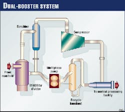
The dual-booster installation is unique in that the system takes advantage of the multiphase twin-screw pump`s flexibility to handle both gas and liquid, and it operates in parallel with a gas compressor to more efficiently boost high GVF well streams (Fig. 5).
Evaluating multiphase boosting
The previous examples show that multiphase boosting is practical and can be applied to a broad range of conditions. However, because multiphase-boosting operating characteristics are not widely understood, evaluating a production system as a potential candidate for a multiphase installation can appear to be daunting.
This process can be simplified by remembering that fundamentally these systems use volumetric pumps, and the capacity and power requirements can be determined with established formulas in conjunction with a simple method of organizing the flow volumes into a flow net, governed by capacities, pressures, and temperatures.
A graphical technique can aid in determining the size and number of pumps, after which calculations determine the power requirements. Some of the special requirements of multiphase pumping systems include working pumps in parallel and handling sediments.
The suggested methods are particularly adaptable to satellite well groups that are ultimately networked through a gathering system into a central processing point. While this discussion includes an example flow station taken from an Orinoco project, the methodology is applicable to all crude types and to all gas fractions.
Volumetric production plan
A multiphase boosting plan is basically a "volumetric" solution. The pumps are positive displacement pumps (twin screw) and are sized with respect to the volumetric throughput they can achieve. Experience has shown that these pumps can move liquids or gas, or any mixtures in between, with no noticeable effects caused by slugging.
The pumps can develop up to 300 psi differential pressure (in the low-pressure types), and up to 900 psi (and in some cases a maximum of 1,200 psi) for the high-pressure versions.
The fastest way to estimate what will be needed is to first establish the total volumetric flow rates of the produced fluids (gas and liquids), expressed at standard conditions, for each year of the project. These volumes should be grouped into the flow streams that will pass through the various gathering points in the field.
The next step is to determine the inlet pressures and temperatures that are required at the wellhead, the battery, at each flow station, and at the central processing plant. Once these are set, then multiphase flow calculations downstream of the flow station will yield the discharge pressures needed, and the corresponding line diameters. These pressure requirements should then be listed for each year.
Next, one should convert the gas volumes from standard conditions into volumes adjusted for the inlet conditions at each flow station, expressing them in terms of liquid equivalents.
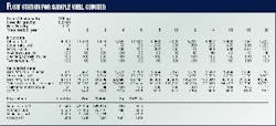
Table 1 shows a sample flow station calculation. Volumes under standard conditions are in the top section, and the inlet volumes are in the calculated data section. The table also shows the associated GVF and power requirement (hp) for each year.
Data analysis
The increase in GVF is mainly associated with production decline and inlet pressure changes. It is not directly related to changes in GOR.
The average GVF is 86.3%, but this oft-cited parameter is not significant for selecting a pump system. Peak values are much more important.
Average horsepower is only interesting when computing the power cost over project life. Peak demands are needed to determine motor sizes and equipment configuration.
In other words, when specifying a pump, it is not sufficient to give an overall range of values and averages. The pumping profile over time is needed.
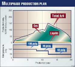
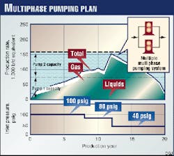
A graphical presentation of the volumetric flow data at inlet conditions is useful for developing a pumping plan (Fig. 6). Note that in this example, the inlet pressure has been lowered after several years to maintain optimum liquid production.
This has a significant effect on the total volumetric "load" at the flow station. It also can affect the pressure differential and horsepower that the station must maintain.
This example emphasizes the importance of considering pressure changes over time when designing the volumetric flow plan. It also implies the importance of flexibility in considering the best pumping solution for this flow plan, because these pressure assumptions can change over time.
Pump parameters
When designing a the multiphase boosting installation, one should first look at the volumetric flow-vs.-time graph, showing both the liquid and gas components for each individual flow station. Then, one should decide on the minimum number of pumps needed per station for redundancy and backup, as well as flow-rate flexibility.
An additional factor to consider for large projects is the interchangeability between flow stations of equipment such as modular size and driver types. Once these parameters are set, the number of pumps and when they will be needed in the plan can be graphically determined very quickly. By overlaying the pumping capacities (Fig. 7) the amount of spare capacity can also be quickly estimated for each time period.
Power estimating
Power is a direct function of flow rate and differential pressure. By knowing the inlet fluid flow rate and using the standard equation for hydraulic horsepower, the power requirement can be readily estimated as:
Then, divide horsepower by 0.85 to obtain a reasonably safe estimate of shaft horsepower.
For multiphase pumps, the greatest horsepower requirement is during the passage of a 100% liquid slug. When this is replaced by a 100% gas slug, the horsepower requirement is less, usually about 7-10% less. The liquid slug is assumed to be passing through the pump at the maximum rate that one intends to operate the pump in that time period.
Volumetric load
If the flow predictions follow the typical expectations for a gassy crude, the volumetric flow rate of gas will increase over the first few years, then it would decline in terms of standard temperature and pressure. This is not the case, however, in volumetric terms expressed at inlet conditions where inlet pressures are expected to decline. Volumes can increase dramatically, as can power requirements.
This usually results in a maximum volumetric flow rate, late in the life of the station, that can cause multiphase pumping costs to escalate. The average GVF will also increase throughout the life of the project, approaching well over 90%.
The typical situation is that gas and inlet pressures are the major factors for defining the volumetric load at the station throughout its life. Changes in liquid volume are, when compared to the gas volumes, relatively small and unimportant when compared to the overall volumes pumped.
Pump plan
In the previous example, it was assumed to limit the horsepower of a pump module to 500 or less, and to use electric-motor drives. The number of pumps was minimized, but at least 100% redundancy was deemed desirable.
Note that the meaning of "redundancy" can vary for a multiphase system according to what is important. If oil flow rates are key, then gas rate can be ignored somewhat, and the pump selection can be considered to be "effectively 100% redundant" when all liquids can be pumped, even though only one pump is operating, as in the pumping plan discussed previously.
If the term means 100% redundant, with no changes in pressure or flow of any phase with the loss of single pump, then three pumps would be needed. One would be an exact spare for the pump out of service. If full, 100% backup is required, four pumps are needed.
A detailed calculation for a pumping strategy with two pumps resulted in two identical pumping systems, each using a twin-rotor pump, driven by 400-hp induction motors.
Each pump is capable of a volumetric pumping range of 80,000-33,000 b/d using variable-frequency drive controls and operating between 1,800 and 750 rpm. The total installed power is 800 hp.
Dual boosting
When multiphase flows contain 85% gas or more, a dual booster installation can be cost effective. Fig. 5 shows how two different types of equipment, a compressor and a multiphase pump, are linked to greatly reduce initial costs, operate at sharply reduced power requirements, and offer enhanced flexibility over the project life, when compared to boosting using multiple multiphase pumps.
These improvements are possible because physically the compressor is much more efficient for boosting gas pressure than the volumetric displacement of a multiphase pump. Normally, over time, gas volumes increase, requiring larger sized or more pumps. This would seem to be good news for pump manufacturers, but the truth is that it causes the escalation of project costs, and the multiphase approach can become uneconomic.
A dual-booster system in such a situation, compared to a multiple multiphase pump installation, can result in dramatic cost improvements. Moreover, operating flexibility and redundancy are increased without requiring large investments.
Not only are the pumps smaller but the compressors are standard types, and in many locations available under rental/leasing plans that add financial flexibility to this option.
Installation plan
The multiphase pump in a dual-booster installation handles the nominal liquid flows, but is usually oversized to manage fluctuating liquid rates. It works in conjunction with the flow divider vessel to accomplish this, leaving most of the compression for the compressor.
When liquid slugs are not being pumped, the pump easily shifts to gas processing and then back to liquids. It is not necessary to change speeds and to control the pump because it can run on whatever phase or phase mixture is available. Moreover, it does not need to work in sync with the compressor. It just adapts and reacts to the ambient inlet and discharge pressures that are set by the compressor or the downstream discharge system.
The pump also picks up liquids from the compressor and combines these with the pumped liquids.
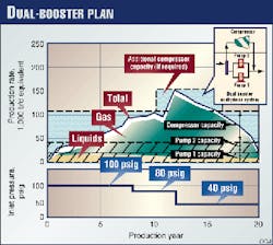
Fig. 8 is a volumetric design for the dual-booster installation. For this plan, the multiphase pump is selected to manage the liquid volume, along with some extra capacity, which usually is at least twice the nominal liquid volumetric rate.
This approach sharply reduces the size, and cost of the installation and at large flow stations, it will reduce the number of pumps required.
The compressor is then selected to handle the volumetric variations caused by GOR and inlet pressure changes. The result is better overall economics compared to the multiphase pumping plan outlined previously.
Example
As an example, two small multiphase pumps were selected for this boosting plan to provide 100% redundancy. Each pump can handle the total liquid flow rate, plus some additional pumping capacity over its range, 8,200-19,000 b/d/pump. Together they can pump 38,000 b/d.
In the first year of operation, this combination is adequate to manage the entire flow without compression. As the gas volume increases, a compressor is added to pick up the additional flow volumes. An additional compressor can be added in the future when and if additional gas appears.
If the compressor is down, the pumps can still pump up to 38,000 b/d of fluids. However, during this mode the inlet pressures will rise above the planned inlet pressure of 100 psi, which may temporarily decrease flows from the wells.
If the compressor is functioning and one pump is down, the remaining pump can handle the liquids plus some gas, and no drop in production will result. No change in inlet pressure would be expected.
Comparison
Based on horsepower comparisons, the estimated capital cost of the redundant dual-booster system will be about 55% of the cost of a marginally redundant twin-pump system. Power operating costs will be about 45-50%.
Annual maintenance costs for the dual booster with the compressor are about the same as for a multiple pump station with larger motors and pumps.
Parallel pumping
In multiphase flow, there is a concern during high GVF flows as to whether two or more multiphase pumps can share equally the inflow of gas and liquids. The underlying reason for this worry is that if one pump is starved for liquids, it will see higher operating temperatures, may operate poorly, or may be damaged due to insufficient liquids in the rotors.
Weatherford Global uses an external liquid charging system that traps flow at the discharge, returning it to the pump. With pumps in parallel, this liquid is metered back to all pumps, ensuring that the necessary minimum liquid is maintained in the flow system of each pump, no matter what the incoming phase distribution may be at an individual pump inlet.
Such a system is much easier to regulate than attempting to manage a liquid/gas splitting system located in the inlet manifold.
This problem is greatly reduced for the dual-booster installation. First, the average gas fraction going through the pump has been substantially reduced, close to 50%. This means more liquid is available per individual pump, causing the pump to run well lubricated and cooler than if it were trying to compress 97% or more of its flow as gas.
The shared liquid trapping system mentioned previously should also be used.
Slugging
Slugging is expected at both the inlet and discharge manifolds, whenever and wherever multiphase flow regimes exist. To minimize the size of the flow divider vessel, it is important for the dual-booster installation design to consider slugging effects.
Small, relatively high-frequency slugging can be expected if the dual booster is at a manifold that receives flows from numerous, nearby wells. This slugging can be handled by a small, compact flow divider.
On the other hand, if the flow arrives through, for example, a 6 to 10-in. line after traveling a long distance, much larger and potentially longer duration slugs may form. These may need a "parking spot" (slug catcher) which will keep the flow divider from being overwhelmed.
Modeling for such systems is helpful in predicting design requirements.
Sediments
Experience with sandy flows has shown that twin-screw pumps will see some increased wear. This wear will result in a loss of pumping capacity as more and more slip flow occurs. This problem can be delayed by adding hardening to the rotors, selecting special rotor liners, and welding on wear layers.
The greater the gas fraction, the more susceptible is the pump to efficiency losses from this type of erosion.
Design considerations
From the previous examples, and based on current experiences, it is evident that when considering a multiphase flow solution, there is much more to evaluate than trying to select a type and size of pump. The design of the surrounding system is highly important, and the system must be tailored to the site conditions.
The inlet pressure as it affects gas volumes will be a principal determinant in equipment selection. Because this change in pressure may occur later in the project life, after the system is installed, it is highly important to anticipate this type of change.
If the GVF at the flow station is 85% or more, then the type of multiphase boosting system (multiple pumps vs. a dual-booster approach) will fundamentally affect the project economics much more than the pump type.
For offshore, it has been shown that the dual booster can offer savings of 30% or more, while on land, these differences may be less and the economics will be affected by the complexity of the operation.
Acknowledgment
The authors want to state that any opinions and explanations in this article are those of the authors and are not necessarily those of Weatherford Global Compression Services L.P.
Authors
Bryan V. Butler is manager of multiphase development for Weatherford Global Compression Services. He has over 30 years' experience in production and the application of hydraulic and multiphase metering and pumping equipment in the oil field.
Butler holds an MS in civil engineering from the California Institute of Technology.
Glen A. Curtis is sales manager for Weatherford Global Compression Services' multiphase systems group. He has over 10 years' experience working with rotating equipment for the oil and gas industry.
Curtis holds a BS in mechanical engineering from Texas A&M University.
