DNV certifies pipe for LNG projects
Det Norske Veritas in early May issued a “Certificate of Fitness for Service” for use in LNG projects to Houston-based ITP InTerPipe’s triple-wall insulated pipe-in-pipe technology.
ITP started developing and qualifying the technology in 1998. Development complied with the DNV technology qualification process as defined in DNV RP-A203, Qualification Procedures for New Technology.
Four major oil companies joined ITP in a joint industry project in 2003 with the objective of qualifying ITP’s pipe design for subsea transportation of LNG. The JIP successfully obtained “Approval in Principle” from the American Bureau of Shipping and “Statement of Feasibility” from Det Norske Veritas for the LNG pipe design for subsea service in 2004.
ITP completed the frontend engineering design study necessary to gain DNV’s certification of fitness in 2006.
The DNV certificate of fitness for service affirms that, at the time of assessment, the new technology is considered fit for service. Certification means that failure modes identified through the process outlined in the DNV offshore service specification, DNV OSS-401, have been properly addressed, and that supporting evidence substantiates that the technology fulfils all stated functional requirements and meets the stated reliability target.
Makeup, capabilities
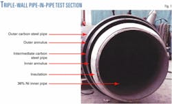
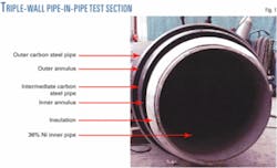
The 2003 JIP fabricated and tested a full-scale, triple wall section (Fig. 1) consisting of:
- A 24-in., 36% Ni steel inner pipe with 40-mm thick insulation.
- A 30-in. carbon steel intermediate pipe.
- A 34-in. carbon steel outer pipe.
As applied in the LNG pipeline configuration, the Izoflex insulation provides an overall U-value of 0.131 w/sq m-°C.
The 18-m test section consisted of a 12-m straight section and a 5D bend, for a total 18-m length. The test section included two full-scale end bulkheads and an inline bulkhead at the base of the bend. The straight section included one 36% nickel steel girth weld. The bend demonstrated the ability to manufacture bends through an induction bending process.
The test program consisted of the following:
- A hydrostatic pressure test at 30 barg and ambient temperature.
- Five thermal cycles from ambient temperature to -196° C. (-320° F.) and 1 barg, including shock cooling of the inner pipe with liquid nitrogen.
- Four boil-off tests at -160° C. (-256° F.) and 17 barg, across a range of inner annulus pressure conditions (OGJ, Nov. 14, 2005, p. 57).
Potential use
One receiving terminal has selected the ITP LNG pipe as its base case design and several other projects are considering the technology for both import and export of LNG, according to DNV.
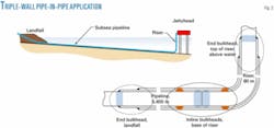
Transporting LNG through subsea or buried pipelines can:
- Eliminate the trestle typically used in such instances.
- Increase security, as the pipeline is buried and thus not visible.
- Increase siting options by allowing loading or offloading further offshore and placement of tanks further inland.
- Decrease environmental and aesthetic consequences.
- Decrease or eliminate the need for dredging.
Fig. 2 provides a basic illustration of how use of this design would yield these benefits.
PlusPetrol SA, Buenos Aires, selected a similar ITP pipe-in-pipe technology in 2002 for use as the onshore and subsea propane and butane loading lines of its Camisea LPG export terminal.
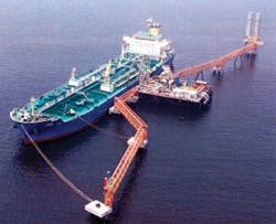
Fig. 3 shows the LPG berth for Camisea at Pisco, Peru. The conventional trestle originally proposed for this project fell victim to local objections. These objections were based on the high visibility of such lines and concern that a trestle would interfere with fishing boat routes. The trestle was also subject to a risk of collision over the anticipated 35-year project life and was higher in cost than the subsea option.
In the end, two 20-in. by 24-in. pipe-in-pipe lines were used to transport propane and butane at temperatures as cold as -49° F. from the Pisco fractionation plant to the offshore berth; 1 km buried onshore and 3 km buried offshore.
The pipelines became operational in September 2004 when the first load of butane was shipped. Field measurements of the thermal performance of the pipe-in-pipe loading system in operation confirmed that designed thermal performance had been achieved.
While the system is designed to circulate product continuously through the cryogenic lines to keep them cold, the system’s thermal performance resulted in such a low boil-off rate that the LPG pipelines can be shut-in between shipments for longer than a week and still maintain operating temperatures (OGJ, Nov. 14, 2005, p. 57).
The Camisea LPG pipelines demonstrate all components of ITP’s LNG pipeline design, construction, and installation except the 36% nickel steel pipe.


