Geosteering precisely places multilaterals in Norway’s Troll field
Eirik Skarsbø, Norsk Hydro Produksjon AS, Bergen, Norway
Klaus Dieter Ernesti, Baker Hughes INTEQ, Stavanger
In Norway’s Troll field, Norsk Hydro Produksjon AS and its service partners drilled the complex Starfish well in June 2005 with five laterals from a single slot. The objective was to position the well bores precisely in thin oil layers to contact more than 13,000 m of the reservoir.
For accurate geosteering, the drilling team designed an integrated bottomhole assembly consisting of a rotary steerable drilling system, acoustic porosity logging LWD system, a real-time drilling dynamics diagnostics service, and an application-specific PDC drill bit. The BHA drilled the precise well paths at 240 m/day in the challenging drilling environment, while office staff in Stavanger monitored drilling operations in real time.
A lubricant additive to the water-based fluid system helped reduce the friction coefficient for faster drilling through the calcite cemented intervals. Two of the laterals were completed with sand control screens and three branches were left barefoot. The well had a gas cap-gas lift valve installed for increased lifting capacity. The lateral junction that joined the sand screens was gas and sand tight (TAML level 5).
Troll field
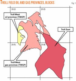
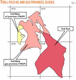
The Troll field is in the Norwegian North Sea, about 80 km west of Bergen at a water depth of about 335 m, covering 700 sq km (Fig. 1). The field is divided into three different fault blocks: the Troll East gas province (TEGP) with only a thin 0-4-m oil column below the gas cap; the Troll West gas province (TWGP), where recoverable oil is found in thin layers from 8-13 m; and the Troll West oil province (TWOP) with a 22-27-m oil column.1
The reservoir consists of a sequence of alternating M-sand and C-sand lithologies. The C-sands are medium-to-coarse grained clean sands with permeability ranging from 1-30 Darcy. The M-sands are fine-grained micaceous sands with permeability’s from 10 md to 1 Darcy.
Initial studies indicated that vertical wells would not provide an economically viable means to produce oil from the thin C-sands. In 1988, Hydro conducted production tests to determine the potential for economic production through horizontal wells. The oil development strategy was implemented at that time to produce the thickest and most productive sands first and steadily exploit the thinner pays with advancing horizontal drilling and multilateral completion technologies.
The oil is currently being produced through 106 wells with 149 horizontal branches. The total length of wellbore is more than 350 km and sand layers as thin as 8 m are being produced.
These efforts have resulted in more than 1.9 billion bbl of expected oil reserves, an increase from the initial estimate of 350 million in 1991. The total oil production from Troll exceeded 1 billion bbl as of March 2005.
Well design
Troll oil wells primarily target the C-sand. The first wells on Troll were drilled horizontally in the TWGP, 1-2 m above the initial oil-water contact to avoid water production. Currently the focus is on restricting gas coning. As a result, the 81⁄2-in. horizontal sections today are drilled 0-0.5 m above the oil-water contact.
The wells are landed horizontally in the reservoir 2 m below the observed oil-water contact. A liner with pre-made windows is then oriented in the reservoir. The windows are placed in the most optimal position for the later drilling of the lateral branches.
The first bilateral well was drilled in 1997. Today, as many as six branches are drilled from one well. The five-branch well described in this article is in the southern part of the TWGP.
Drilling technology evolution
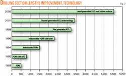
Extended-reach drilling has been a key enabler of Troll oilfield development. Fig. 2 shows steady improvement in the total vertical depth tolerance and horizontal section length with each successive generation of drilling technology.2
During the first years of drilling on the Troll West oil province, drilling assemblies included a positive-displacement motor (PDM) with logging while drilling (LWD) sensors 15-20 m behind the bit. Due to limitations in orienting and steering, this BHA was able to drill horizontal sections only about 800 m long.
In 1994, Hydro used an instrumented PDM in the Troll field. The LWD equipment measured the inclination 4.1 m behind the bit. Gamma ray and resistivity sensors were placed, respectively, 5 m and 6 m behind the bit. This combination met the TVD control requirements and extended the horizontal section reach to 1,500 m.
In 1996, engineers incorporated a hydraulic thruster to decouple the BHA hydraulically from the drill string and ensure weight transfer to the bit during steering. This advance increased the horizontal section length to 2,300 m and improved the TVD control to ±1.0 m.
In 1998, rotary steerable systems (RSS) were introduced with the commencement of drilling on the TWGP. RSS enhanced TVD control and improved WOB transfer, extending the achievable section length to 3,200 m.
In 2002, Troll drilling switched to a modular RSS, which made it possible to customize the BHA to address drilling-related challenges. For example, a stiff BHA was used to reduce tortuosity and improve directional control through the calcite-rich formations. A more flexible BHA was used when the RSS was rotated over a whipstock to reduce the load exposure on the individual BHA components.
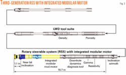
With the introduction of the third-generation RSS, TVD tolerance was reduced to ±0.5 m and section length increased to 5,500 m (Fig. 3). This latest generation system includes several formation-evaluation services to enhance directional control and wellbore-placement capabilities.3 Azimuthal gamma and azimuthal density measurements are made to identify formation layers and their dip and strike. An integrated PDM has been added to the RSS to allow drilling at rates of penetration comparable to those achieved with the standard RSS but with only half the string rotation.
BHA dynamics diagnosis
In 2001, an advanced drilling diagnosis service was introduced to adapt drilling parameters better to changing downhole conditions. The service consists of a downhole drilling-dynamics-diagnosis tool and a trained engineer to perform active data analysis. The tool measures parameters such as lateral and axial vibrations, stick-slip, downhole bending moments, WOB and torque, whirl, torque shocks, pressure, and temperature.
The measured data are transmitted to the surface with MWD pulse telemetry. The engineer analyzes the data from the perspective of maximum energy transfer and minimal stress on the BHA and recommends appropriate changes in the drilling parameters. The downhole bending-moment measurements have been particularly useful in reducing the severity of local doglegs. This diagnostic tool is also being used for steering while turning the well azimuthally in the horizontal plane.
Drill bit advances
In the context of the Troll field, drill bit advances have been driven by the demand for improved drilling performance in hard, calcite-cemented formations. Roller cone bits had to be used before the RSS applications, as PDC bits were too aggressive while steering and orienting. Bit coning and teeth erosion was common due to the abrasive sand formations. Different coatings and hard facings on the cone shell, as well as optimized bit hydraulics, increased the life of the roller cone bits.
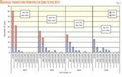
With the introduction of BHAs with RSS and PDC bits, the drilling team had to contend with cutter wear and ring-outs as a consequence of bit instability. Continuous optimization of the cutter design, bit hydraulics, and gauge configurations for the Troll-specific BHA has enhanced drilling performance. As a result, there has been a gradual increase in PDC bit usage to about 91% in 2005 from 26% in 2002.2 Roller cone bits are now used only for drilling the hardest calcite cemented intervals (Fig. 4).
Water-based mud technology
Troll wells are drilled from spud to TD with environmentally compliant water-based mud systems. The 36 in. and 24-in. diameter hole sections are drilled with returns to seabed using seawater and highly viscous bentonite sweeps.
Next, the top-hole sections are displaced with weighted mud before running casing to prevent hole instability. The 171⁄2 in. and 121⁄4-in. sections are drilled with KCl mud with high salt concentration and glycol to stabilize the formation. Before 2001, horizontal sections were drilled with 1.25 sp gr NaCl mud.
As horizontal section lengths became longer, 1.15 sp gr CaCO3 polymer mud was used to minimize the risk of lost circulation due to high ECD. The mud system has now been refined to a 1.12 sp gr system to further reduce ECD.
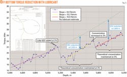
As Troll wells are drilled principally through calcite-cemented intervals, a lubricant additive is necessary to reach target depths due to torque restrictions. Water-based muds generally have higher friction coefficients than oil-based muds. A water-based lubricant is used at 2-3% by volume. The resulting torque reduction is typically between 20-30% (Fig. 5).
Multilateral completions
Multilateral well technology (MLT) is a cost-effective solution for reservoir drainage in the Troll field. The first MLT well was drilled in the Troll field from a semisubmersible rig in 1997. Three bilateral wells were initially drilled and completed with cemented junctions.
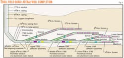
Since then, a more efficient and risk-reducing MLT solution has been developed. Up to three junctions have been installed in the same well to expose up to 16,000 m of reservoir (Fig. 6). Compared to conventional wells, MLT wells have improved the reservoir recovery.
In preparation for the installation of windows for the laterals, a horizontal section is drilled with a 121⁄4-in. bit and a 131⁄2-in. under-reamer. A 103⁄4-in. liner with a 95⁄8-in. bottom section, including premachined openings for multilateral branches, is placed horizontally 2-3 m below the OWC and oriented in place. The liner has pre-installed latches that fit the whipstocks used while the branches are drilled.
After a branch is drilled, the whipstock is pulled out, and a deflector with an open bore to the well below is installed in the same branch. The sand screens (65⁄8-in. screen with an open design to prevent plugging from fines) are then run and guided into the branch by the deflector. The lateral junction, placed on top of the screen section, is strung through the deflector and into the wellbore below, creating a sealed junction. The sequence is repeated to complete the next branch.
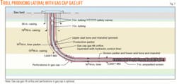
All wells drilled through the gas cap have equipment installed that allows the gas cap to enter the tubing through perforations in the build-up casing. Fig. 7 shows a producer with gas cap-gas lift (GCGL) equipment.
Starfish well
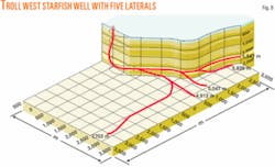
The application of advanced drilling and completion technologies on the Troll West gas province reached a new milestone in June 2005 with the construction of a “Starfish” multilateral well with five extended-reach horizontal sections (Fig. 8).
Hydro and its service partners-Baker Hughes INTEQ, Hughes Christensen, Baker Hughes Drilling Fluids, Baker Oil Tools, and Halliburton Energy Service-performed detailed engineering and modeling to plan the complex well trajectories and drilling and completion procedures. The integrated drilling BHA included the AutoTrak G3.0 RSS, LithoTrak LWD system, CoPilot drilling dynamics system, and Genesis PDC bits.
PerFLOW CM CaCO3 polymer drilling and completion fluids were used with Lube 622 lubricating additive. Drilling team staff monitored the drilling progress and provided guidance to the crew in real time from the BEACON remote operations center in Stavanger.
The longest Troll well (7,703 m MD) was drilled at the rate of 240 m/day. Only six RSS tool strings were needed to drill the five laterals that provide 13,542 m of contact with the reservoir sands. Two of the laterals were completed with Exclude2 2000 screens (1,961 m and 3,709 m) and gas lift valves. Baker Oil Tools installed the screens through a single-trip completion.
A Halliburton FlexRite MLT system was installed to create a sand-free and gastight junction between the two branches completed with sand screens. In order to clean out the completion fluid from the three barefoot well sections without plugging the screens, the junctions between open hole and screen were equipped with timer-controlled sleeves.
The sleeves would close after the initial cleanup phase. Radioactive tracer materials were placed in two of the three, openhole branches and in all three clean out valves. During production start up, analysis of the oil produced proved the openhole branches were contributing to production.
Aggressive technology development has enabled Hydro to produce more than a billion barrels from what was once termed an economically unfeasible oil field because of its thin productive reservoir sands. Hydro currently plans to reach “Troll 300”-to produce a total of 300 million standard cu m (1.9 billion bbl) of oil from Troll-but continued development of drilling and well technology could extend even this volume.
Acknowledgments
The authors thank the Troll Oil license partners for their approval to publish this article. The partners are ConocoPhillips Norge AS, Total E&P Norge AS, AS Norske Shell, Norsk Hydro Produksjon AS, Statoil ASA, and Petoro AS (Norwegian State).✦
References
1. Madsen, T., and Abtahi, M., “Handling the Oil Zone on Troll,” paper 17109 presented at the Offshore Technology Conference, Houston, May 2-5, 2005.
2. Skarsbø, E., Solveit, R.E., and Ernesti, K.D., “Troll Oil Drilling: Step Changes through Application of Front End Technology,” paper 17112, Offshore Technology Conference, Houston, May 2-5, 2005.
3. Hahne, U., Risdal, G., Ruszka, J., and Wahlen, L.S., “Integrated BHA Concept of the Latest Generation Rotary Closed-Loop System for Holes Size 57⁄8-in. to 181⁄4-in.,” IADC/SPE paper 87168 presented at the IADC/SPE Drilling Conference, Dallas, Mar. 2-4, 2004.
The authors
Eirik Skarsbø (Eirik.Skarsbo @hydro.com) is a senior drilling engineer for Norsk Hydro in Bergen, Norway. Currently assigned to the West Venture, his main responsibility for the last 3 years has been well planning on Troll. He studied geology at the University of Bergen and has worked in the oil industry since 1988. Skarsbø started his career as a mud logger, data operator, and well site geologist for Baker Hughes INTEQ and continued as operations geologist with Saga Petroleum ASA. He joined Hydro as a drilling supervisor in 2000.
Klaus Dieter Ernesti ([email protected]) is the applications engineering manager for Baker Hughes INTEQ based in Stavanger, Norway. He joined INTEQ in 1995 in Celle, Germany, after obtaining his diploma in mechanical engineering from FH Braunschweig/Wolfenbuettel, Germany (1995). During his 10-year career, Ernesti has served as a development engineer, group leader in operational engineering, and technical adviser. He is a member of the SPE section board in Stavanger and a member of the VDI (Society of German Engineers).
