New process controls BTEX in direct-fired TEG reboilers
A process for combusting all vapors released from the glycol in a triethylene glycol (TEG) reboiler has been developed and successfully employed. The process, StripBurn, ensures 100% combustion in contrast to the method of injecting the volatile organic compounds (VOCs) into the reboiler’s stack.
It also consumes less fuel because glycol flow rates can be lower with use of stripping gas and the complete combustion of “noncondensables.” In addition, the larger-than-normal amount of gas mixed with VOCs results in less VOC in the condensed water vapor from the overheads because the vapor-liquid equilibrium is shifted in such a way as to minimize the condensation of the VOCs. Thus, the disposal water will contain significantly lower quantities of undesirable components.
Finally, the process precludes environmental testing of the facility for atmospheric discharge of VOCs because no VOCs are released to the atmosphere as is often the case with conventional technology.
The basic idea of StripBurn is to use the flash gas from the TEG returning from the contact tower plus make-up gas as stripping gas in the reboiler and then as fuel for the reboiler. It provides complete combustion of benzene, toluene, ethylbenzene, and xylene (BTEX) components and decreases the fuel cost for gas dehydration.
VOC emission control
BTEX and other VOC emissions pose an environmental problem for the natural gas industry, since one of the components is carcinogenic and all are normally present in natural gas streams.
The most common gas dehydration system uses TEG to adsorb water from the gas. Unfortunately, TEG also adsorbs VOCs, which are driven off with the water in the reboiler. With the number of glycol dehydration systems in use exceeding 40,000 in the US and the estimated amounts of VOCs absorbed by them, many state governments now regulate emissions from glycol dehydration units.
There are two main approaches to BTEX control for natural gas production. The first is to burn BTEX components in a flare or as fuel; the second is to inject them back into the sales-gas stream. There are several variations of each approach.1
The most commonly employed options, due to simplicity of operation and cost, use a cooling device on the reboiler still column’s exiting stream to condense the water and VOCs with the noncondensables being injected into the reboiler in a separate burner.
Such a procedure presents two major concerns:
- The almost atmospheric pressure does not provide adequate mixing of air and VOCs to ensure complete combustion. Many assume that the main burner will combust the noncondensables. But induced-draft burners operate intermittently and noncondensables are simply emitted out the stack instead of the flare or vent system during periods when the reboiler system is not operating.
- During the periods of minimal inflow to the reboiler while the condenser is operating, a slight vacuum is pulled by the condensing of vapors because no incoming vapors are available to occupy the space. This allows oxygen entrainment and severe levels of corrosion. Some companies actually build their condensing separators from fiberglass to overcome this problem.
Other methods have been deployed to combat these problems, such as compression or eduction, which increase the pressure and allow disposal to flare or fuel. These add additional capital costs, consume more energy, and increase operational complexity.
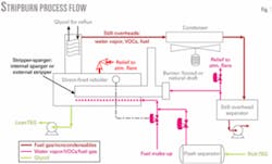
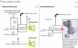
The process described in this article cools the still overhead vapors and uses a mixture of noncondensable vapors and make-up gas as fuel in the main burner (Fig.1). This ensures 100% combustion of the VOCs while maintaining a positive pressure in the still overhead system. The main burner can be either natural or forced draft while the fuel gas can be injected into a sparger pipe or an external stripper column, depending on the dewpoint depression requirements.
Note that a StripBurn natural-draft burner imposes 3-5 psi backpressure on the reboiler to provide sufficient pressure for efficient operation of the burner, while the forced-draft system imposes only a few ounces.
Many of the competing control systems require frequent sampling to ensure that the required percentage of the VOC vapors is indeed being kept from release into the atmosphere. The intimate mixing of the VOCs with the primary fuel gas ensures complete combustion. Therefore, it becomes a fuel with a slightly elevated BTEX content and likely will not require stack sampling for BTEX monitoring. This system also reduces the amount of VOCs in the condensed water, due to a reduced partial pressure of the gas.
Mixing gases
A predecessor of PetroDesigns conceived the concept of mixing fuel gas with stripping gas, with or without flash gas, condensing the liquids, and burning the remainder in a forced-draft burner. As opposed to a natural-draft burner, the forced-draft burner was deemed necessary, since it requires only inches of pressure for operation, has a very large turndown ratio, and easily adjusts the air-fuel ratio necessary for varying BTU contents. At the time, many possible locations had no power, and clients were averse to using forced-draft burners because natural-draft burners were so prevalent.
Since then, forced-draft burners are now better accepted because of the use of such electronic controls as programmable logic control systems, recommendations by the US Environmental Protection agency and other emission-control authorities for the use of electric-motor-driven glycol pumps instead of gas powered, and more concern for nitrous oxide controls on burners.
Working on a joint project, PetroDesigns, Marrero, La., and Gly-Tech Services Inc., Harvey, La., a specialist in glycol-unit maintenance and operations, realized that both options, natural draft and forced draft, had their own applications: natural draft for systems with need for little turndown and the forced draft where turndown is advantageous.
Gas balance
The following discussion reviews the process logic associated with the system, covering flash gas and fuel gas uses along with the need for and necessary quantities of stripping gas. An updated version of PC GLYCOL, called “VBA Glycol,” was used for most of the process and mechanical calculations.2 3
The need to burn all of the hydrocarbons efficiently in the still column overhead stream places several constraints on the design. These can be easily met, however, and the result is an economically efficient system with nearly zero BTEX emissions.
The fuel consists of the flash from the glycol returning from the contactor plus make-up from an outside source if the flash is inadequate to meet the fuel or stripping gas requirements. If flash gas or stripping gas volumes exceed the fuel requirement, an auxiliary burner would be required to burn the excess gas or, preferably, alternative control methods considered.
It is, therefore, desirable to design the system so that the fuel-stripping gas requirements exceed the flash gas rate. As will be shown, this can be done for the majority of the cases.
Fuel gas
Most of the fuel-gas requirements for a given system depend on the amount of water being removed, the TEG circulation rate needed to remove the water and accomplish the desired outlet water content, and the size of the glycol-glycol exchangers. The entrained VOCs are a very small factor in the overall load.
For glycol units, a common design rating is the number of gallons of glycol circulated per pound of water removed. Much of the literature recommends an outdated 3 gal/lb, a value commonly used in the 1960s and 1970s.
The advent of structured packing allowing smaller towers and more contacts without inordinately large vessels and a better understanding of the equilibrium data for the TEG-natural gas-H2O system allow ratios as low as 0.50 gal/lb to be successfully employed.
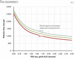
Fig. 2 plots the fuel requirements for the range 0.5-3.0 gal/lb and for 50, 75, and 100° F. glycol-glycol exchanger approach temperatures.
The values are approximate, since the heat transfer coefficient (U value) for the glycol-glycol exchangers will vary with the flow rate. This does not present a substantial variation, however, and as Fig. 2 shows, the variation as a percent of the total lessens as the TEG rate approaches 0.50 gal/lb.
Flash gas
The most interesting feature from Fig. 2 is the rapid increase in the btu/gal requirement at the lower gal/lb circulation rates. This assists greatly in cases in which burning the associated flash gas that returns with the glycol is desired. This entrained gas is primarily methane due to its being the prime constituent in the gas stream, but it also contains VOCs and heavier hydrocarbons.
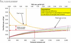
Since the rate of entrainment (or solution gas) is a function of the gas analysis, as well as the contactor’s operating pressure and temperature, the actual values will vary from project to project. Fig. 3 shows the flash gas for two different compositions, pure methane and a typical 0.70 sp gr gas with VOC components included.
HYSYS V. 3.1 was used to compute the flash gases in Fig. 3. This analysis showed an interesting phenomenon for the absorption of the light hydrocarbons (methane, ethane, and propane) in the TEG. As one would expect, the absorption increased as the pressure increased; but, unexpectedly, the absorption also increased as the temperature increased. Further investigation showed this indeed to be the case.4 5
The above flash gas assumes standard positive-displacement pumps and does not include gas associated with gas-powered pumps such as Kimray. In most cases, the use of gas-powered pumps will result in more return gas than is required by the reboiler. Although the StripBurn process could combust much of the gas, there will still be some vapors to flare. As noted elsewhere, when compression is unavailable, motor driven pumps are recommended.6
Comparison: fuel-flash ratio
The concept of this process is to burn all the vapors from the returning glycol, including the flash gas. To do this, there must be less flash gas than fuel gas.
Fig. 4 shows fuel and flash gas for a typical system in which the theoretical contacts in the contactor and the lean TEG concentration require a lean-glycol circulation rate of 1.25 gal/lb. For this case, about 0.70 scf/gal gas is required to make up the difference in required fuel gas and returning flash gas. Make-up gas and flash gas will both be used for stripping gas, thereby allowing for a lower glycol circulation rate.
Stripping gas
A common method for rating the difficulty of a dehydration requirement is the required dewpoint depression. Fig. 5a shows the dewpoint vs. water content for 500, 1,000, and 1,500 psi, while Fig. 5b shows the equivalent dewpoint depression for a 120º F. contact temperature.
The need for stripping gas is determined by the gas operating conditions (temperature, pressure, water content in and out), number of theoretical contacts (height of packing or number trays), TEG rate, and the lean TEG concentration. Fig. 6 shows a typical dewpoint depression vs. lean TEG circulation rate for various lean TEG concentrations.
Since reboiler temperatures of 390º F. result in about 98.9% lean TEG, the case in Fig. 6a shows that stripping gas will be required for depressions at greater than 87-88º F. Using stripping gas curves such as shown in Fig. 6b can determine the lean TEG requirement. For example, should the dewpoint depression requirement be 95º F., a lean TEG concentration of 99.5% will be required. To achieve this concentration and maintain a stripping rate less than the total fuel requirement will require a counter-current stripper with slightly more than 1.0 theoretical contacts.
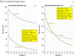
The number of contacts in the contactor also can determine the relationship of the flash and stripping gas to the fuel gas. Fig. 7 shows this effect, Fig. 7a showing a less stringent dewpoint depression requirement for which the fuel gas is always greater. Fig. 7b shows a case in which a minimum of 13 ft of packing is required to reduce the stripping-gas rate to a value less than the fuel-gas rate.
Adding more packing in the contactor or stripper, and thereby increasing the theoretical contacts in either or both, reduces the cases for which the flash gas is greater than the required fuel gas. When this occurs, such as for very high dewpoint depression requirements, other options should be considered, e.g., use of the pressurized reconcentration system or compression of the excess overhead vapors, either at flash pressure or reboiler pressure.
Burners, control
The key to the system described here lies in the burners, in that they must burn continuously and ensure combustion of the VOCs. The two types of burners used in oil and gas field processing are natural draft and forced draft. The following reviews the design features and recommends cases in which each is to be properly applied.
Natural-draft burners are the most common, since the capital cost is low, fuel efficiency is adequate, and no power is required. The device is relatively simple with the burner draft pulling in enough air to allow for combustion of the fuel gas that is introduced through a mixing device.
The key to the efficiency is to ensure that the air-gas ratio stays within flammability limits while combustion is occurring, the stoichiometric value being about 10:1, air to fuel gas. Since the draft depends primarily on the heat in the burner stack, the air rate does not vary drastically so that the turndown is limited. Excess air rates of 10-20% are also required to ensure complete combustion, thereby reducing the overall efficiency to 60-70%.
For units in which the glycol rate and water removal will be somewhat constant, the natural-draft burner will perform well. The reboiler pressure needs to be higher, however, to allow for adequate pressure drop and velocity through the burner nozzle (orifice) to allow for proper mixing of the air and fuel. For a properly designed burner, this pressure can be as low as 3 psi with 5 psi being preferred.
Forced-draft burners have blowers or fans that produce 2-6 in. of air pressure to induce high air velocity, creating a lot of turbulence in the firebox with more uniform heating. This increased air pressure allows the reduction of excess air to the 5-10% range and allows burner efficiencies of 75%. They also are quieter, reduce NOx emissions, and have a much better turndown ratio (40:1 or greater).
There are many manufacturers of forced-draft burners, many offering complete package solutions. Although they appear complex, the current solid-state control systems make them simple to operate while increasing the reliability.
Control schemes
The method recommended for controlling the burners is fairly simple (Fig. 8). The natural-draft burners are slightly more complex due to the lower turndown capability. The flash gas is allowed to go always to the burner with the temperature controller allowing make-up gas as required. A manual globe valve is suggested for cases in which the flash gas may be inadequate to maintain minimum fire.
To provide increased flexibility, a separate on-off burner is recommended with the control being from the reboiler’s temperature controller. This burner can be a “standard design” for a 10-12 psi fuel-gas pressure.
The forced-draft burner is designed to burn continually whatever gas is being sent to it at a constant air-fuel ratio. This ratio can easily be set to ensure adequate combustion even if the fuel is very rich.
In the field
In April 2004, a precursor to the natural-draft StripBurn system was introduced to ExxonMobil Corp. as a means to eliminate glycol reboiler still-column-vent emissions at the 84-MMcfd St. Regis gas plant, Jay, Fla. The existing system had used nitrogen for stripping with the still column vent emissions being piped to a forced-draft aerial cooler for condensation of water vapor and VOCs. The non-condensable hydrocarbons and N2 were vented to atmosphere, but a change in the air permit required elimination of the hydrocarbon vent.
To eliminate emissions, natural gas was used in the countercurrent stripping column in place of the N2 and the noncondensables after the cooler were routed to a specially sized low-pressure burner assembly and used as primary fuel. The burner assembly was sized to fit in the existing burner’s flame arrestor housing.
The stripping-gas rate was set to provide a continuous burn in the new burner, while the glycol circulation rate was set slightly higher than process requirements for dewpoint depression. This arrangement ensured heat-duty requirements slightly exceeded those of the new burner. The existing burner, operating normally, cycled on and off as required. The system has operated reliably since start-up.
In August 2004, Kinder Morgan Energy Partners LP contacted Gly-Tech about its Fandango gas plant in Zapata Countys, Tex. Kinder Morgan indicated that during hotter summer months, the inlet-gas temperature to its glycol contactor often exceeded 140º F., requiring a glycol purity of 99.75% or greater to meet dewpoint requirements. The unit was already equipped with a condenser and sump for liquids collection; an external countercurrent-stripping column was added.
The StripBurn system was employed to recover the stripping gas so that enough packing height was provided in the stripper to allow the desired TEG concentration to be met with <2 scf/gal gas, a rate that requires a slight amount of supplemental fuel gas. So that the gas could be burned in a natural-draft burner, the reboiler was reinforced to allow for operation at 3-4 psi. The existing natural-draft burner was replaced with one designed for the low pressure, while a supplemental fuel-gas line with flow controlled by the existing temperature controller was added.
The unit operated as expected and is still in service. As part of an overall upgrade of its Moss Bluff facility outside Liberty, Tex., Duke Energy Field Services in early 2005 expressed interest in the natural-draft StripBurn system. The 100% vapor-recovery aspect solved an air-quality issue, while use of the recovered off gas as the primary fuel source for the glycol reboiler promised a quick return on investment.
In December 2005, a VOC condenser unit was installed and modifications were made to upgrade the reboiler and surge tank’s operating pressures to about 4 psi. A newly installed flame arrestor, housing two low-pressure burners, was installed.
The flash gas from the glycol-condensate-gas separator was piped to a fuel-gas scrubber with additional dehydrated gas being added as required. The flash gas is supplemented by dehydrated gas and used both as fuel for the primary burner and as stripping gas. The stripping gas, along with the non-condensable hydrocarbons from the Still Pure unit, fuels the off gas burner.
The system is in service at this time.
References
- “Control of Aromatics Emission for Glycol Dehydration Units: A Look at Novel Approaches,” www.gastechnology.org.
- Hicks, R., and Senules, E. A., “New gas-water-TEG equilibria,” Hydrocarbon Processing, April 1991, p. 55-58.
- Youn, K.C., and Hicks, R., “Improved Program for Natural Gas Dehydration with TEG,” 65th Annual GPA Convention, Mar. 12-13, 1991.
- Private correspondence, Hyprotech, Apr. 4, 2005.
- Nassar, Vivian, Bullin, Jerry A., and Lyddon, Lili G., “Solubility of Light Hydrocarbons in Physical Solvents,” Bryan Research & Engineering Inc., www.bre.com.
- “Minimizing Methane Emissions from Glycol Dehydrators - Lessons Learned from Natural Gas STAR,” PowerPoint presentation, www.epa.gov
The authors
Ralph Hicks ([email protected]) is president of PetroDesigns. He worked for Shell Oil Co. 1968-74 as a facilities engineer and C-E Natco 1974-81 as an engineering manager. From 1981 to 2000, he managed his own companies that were all involved in the design and fabrication of oil and gas processing facilities. Hicks holds a BS (cum laude; 1965) in electrical engineering from Louisiana Tech University, Ruston.
Dale Gallaher is a senior staff engineer at PetroDesigns. He worked for Shell 1974-98 as a facilities project engineer on facility projects in the Gulf of Mexico and overseas. He holds a BS (1962) in physics and an MS (1968) in electrical engineering from Oregon State University, Corvallis, and an MS (1989) in computer engineering from Tulane University, New Orleans.
Allen Logue is senior vice-president of engineering for Gly-Tech, Harvey, La., and is responsible for projects, engineering and seminars/operations training for oil and gas company personnel. From 1976 to 1987, Logue worked for C-E Natco, training as a field services technician and then becoming supervisor of chemical sales and services for the Harvey, La., division. He has presented glycol dehydration seminars worldwide; his presentation is recognized by Louisiana State University as an accredited course in its facilities specialist program.
