LIQUIDS ENTRAINMENT - Conlusion: In-line cyclonic technology remedies compressor liquid ingestion problem
This is the final of three articles that describe BP’s experience with reciprocating compressor damage from liquids intrusion at two facilities, in Oklahoma and Alaska.
Part 1 of the series (OGJ, May 18, 2009, p. 46) discussed the role of changing operating conditions in leading to compressor damage and reviewed details of the Oklahoma incident.
The second article reviewed the validation of CFD modeling by on line laser isokinetic probe sampling for liquid entrainment and the impact of NGL solubility in compressor lube oil.
This concluding article examines the use of state-of-the-art inline cyclonic separation technology to mitigate liquid entrainment.
BP owns and operates the Milne Point oil production facility on Alaska’s North Slope where processing facilities are enclosed in heated, adjoining modules. The gas compression module houses two 3,450-hp reciprocating compressors.
Over time, the frequency and severity of compressor component failures increased. Intense examination identified both mechanical and process-related causes for the failures, including entrainment of water and NGLs in the compressor suction.
Options rejected
Various options were evaluated to prevent liquids from entering Big A/B compressors. Of those rejected, reasons for elimination included technical infeasibility, technical risk, and economic uncertainty.
New scrubbers
Installation of new suction scrubbers is technically feasible to eliminate the liquid entrainment found with the existing suction scrubbers. Space limitations, however, precluded new scrubbers being much taller than existing scrubbers. Although this may have been a problem for a conventional scrubber with a horizontal mesh pad to reduce liquid entrainment, newer scrubber technology works within available space constraints.
To eliminate condensation of additional liquids downstream of the scrubbers, this option would also have required removal and replacement of all existing insulation and abandoned heat tracing between the suction scrubbers and compressors. Total installed cost of this option differed little from the selected demister option.
The economic risk of excessive downtime ruled out this option. Because scrubber replacement would require a complete field shutdown, economic evaluation of this option had to include any lost or deferred production that could not be sheltered by a normal, planned turnaround. Even relatively short added downtime would be costly.
In this instance, dual factors made the risk unacceptable. First, scrubber replacement within a crowded module is not routine, which limits the quality of any estimate of time required to complete the task. Second, BP Alaska has adopted strict control-of-work procedures that limit the amount and types of work that can be performed concurrently inside a process module.
Recent experience has shown that even with more rigorous planning, plant turnarounds take more time than they would without the new procedures.
New internals
Replacement of scrubber internals was an alternative to new scrubbers. As with new scrubbers, this option required complete removal and replacement of all downstream insulation and heat tracing. It was rejected both for economic and technical uncertainty.
Economic risk is similar to that for the new scrubber option. Estimation of time to replace internals would probably be somewhat more accurate than for scrubber replacement, but all such estimation would have to be in the absence of physical inspection of each vessel’s interior.
As with scrubber replacement, this option would also require a complete field shutdown with total loss of production. Also, the same concerns with the non-routine nature of the task and control-of-work procedures apply here as well.
Technical risk is always present in a separator retrofit. The Big A/B suction scrubbers were already retrofitted once in 1995. Current scrubber performance does not meet the process specification for liquid entrainment guaranteed for that retrofit. Advancements in separator design technology over the last 10-20 years, however, afford a greater chance that a new retrofit would be more successful than the 1995 upgrade.
If no other technically viable option were available that could be installed with less economic risk, then a more detailed evaluation would have been performed to choose between scrubber replacement or retrofit.
A third option was chosen, however, which does not require a full field shutdown for installation and removes the technical risk associated with replacement of scrubber internals. The chosen option also significantly reduces insulation and heat trace requirements, as described presently.
Suction gas superheating
Gas turbines are extremely sensitive to liquid entrainment. Vendors normally require gaseous fuel to be superheated to at least 50° F. above the hydrocarbon and water dewpoints to prevent any possibility of liquids entrainment. Such a stringent specification is not applicable to compressors, which are normally only required to be supplied with clean, dry gas.
On the other hand, superheating of compressor suction gas would most certainly eliminate problems associated with liquid entrainment. Milne Point has an adequate supply of heating glycol that could be used as a heat source for superheating the Big A/B suction streams. This option was briefly considered but rejected for technical and logistical reasons.
Technically, the option is infeasible because the compressor discharge temperature is normally 260-265° F., with an upper limit of 275° F. Current discharge temperatures cannot be increased and still retain a reasonable margin of safety. Alternatively, gas cooler limitations and potential for hydrate formation do not allow the suction scrubbers to be operated at lower temperatures as a means of lowering normal discharge temperatures.
Logistically, there is no available space in the module to install superheaters. Two heaters would be required, one for each of the two suction scrubber’s overhead vapor streams. Each heater would have to be sized to handle 36 MMscfd. In addition, to ensure proper heater operation, liquid knockout vessels would be required to prevent liquids from entering the heaters.
Automating bottle drains
Manually operated drain valves were installed on all Big A/B suction bottles and on the discharge bottles of cylinder Nos. 1 and 2 during the April 2007 rebuild of Big A. Liquids are currently drained from these vessels daily. This practice will continue until inline demisters are installed immediately upstream of the suction bottles.
An early idea was to automate these drain valves as a potential solution to the problem of liquids getting into the compressor cylinders. This option was rejected for technical reasons.
First, these vessels were designed to dampen pulsations, not to separate liquids and vapor. As such, these bottles are not amenable to liquid-level detection and control. Second, even though each of these bottles has an internal weir that captures some liquids, the weirs are designed with weep holes that allow any captured liquids to drain slowly through to the other side and enter the compressor cylinder.
Routine operation of pulsation bottle drains has been and still is an important step in minimizing the ongoing infiltration of liquids into Big A/B cylinders. But it is only a temporary measure that is insufficient to prevent all liquids from entering the compressors and causing mechanical damage.
Solution
The solution to Milne Point’s entrained liquids problem consists of several interrelated actions. Many of these have already been implemented, which has considerably reduced the frequency and severity of liquids-related events.
All remaining actions will be completed by the end of summer 2009.
Operational procedure
During periods of high cylinder knocking, plant operators tried various ways to reduce knocking by optimizing compressor scrubber operation. These efforts generally included changing the upstream gas cooler’s discharge temperature set point and lowering the scrubber’s liquid level. Such operational changes yielded mixed results, but more importantly, provided valuable feedback to allow proper operating guidelines to be established.
One important lesson of these operator interventions was undesirable effects of setting the gas cooler’s discharge temperatures too high or too low.
If the temperature were too low, liquids formed more rapidly than the scrubbers could dump them. Operators had to open manual bypass valves to reduce liquids to a safe level. If the temperature were raised too high, the gas exiting the scrubbers, being much richer and warmer, condensed rapidly in the cooler downstream piping. This was accompanied by an increase in knocking that did not stabilize until the downstream piping warmed enough to reduce the rate of condensation.
Operating data and process simulation results helped establish a safe operating temperature range of 75-95° F. for the scrubbers. Except during severe ambient conditions that affect gas cooler operations, temperatures are now normally maintained between 80-85° F. Also, if and when the gas cooler’s temperature set point changes are required, operators now make them gradually if possible. This practice minimizes the condensation of liquids in downstream piping.
Concerns with the existing level-control system capability prevented permanent changes to normal scrubber liquid level. This will be done, however, during the scrubber instrumentation upgrade to be installed during the summer 2009 plant turnaround.
Control logic reconfig
Early process analysis of compressor scrubber operation revealed that the temperature of the process gas exiting the upstream aerial gas coolers fluctuated considerably and was often off its set point. This was due to the temperature control scheme employed for the gas coolers, which set the cooler plenum temperature as the primary control variable and the process gas temperature as secondary. This resulted in a fairly steady plenum temperature with an often unstable process gas temperature.
Operating experience had already established the importance of maintaining a stable scrubber temperature, which was not possible with such a temperature control scheme. Discussions with plant automation technicians confirmed that the plenum temperature did not need to be maintained at a constant temperature but only that it could not be allowed to drop below a specified minimum temperature to prevent hydrate formation in the gas cooler tubes.
The gas cooler’s temperature control scheme was modified to make the process gas temperature the primary control variable. The plenum temperature was allowed to fluctuate as necessary to maintain the process gas temperature, subject only to remaining above its specified minimum temperature. This control change resulted in a more stable operation of the compressor suction scrubbers.
Level system upgrade
Suction scrubbers V-5501 and V-5511 are currently equipped with local, pneumatic level-control instruments and level switches for alarm and shutdown. Because the level-control systems for these scrubbers are not tied into the plant’s basic process control system, control room operators are unable to monitor vessel levels.
Under certain process conditions, liquid levels can rise and fall quite rapidly, with no indication to the control room until a high or low level alarm is triggered. Liquid levels occasionally rise so fast that the current level control valves cannot reduce the level, requiring an operator to open a manual bypass.
In late 2007, the Milne Point facility was shut down when a high-level shutdown switch on one of the scrubbers tripped. Normally, this event would have been preceded by a high-level alarm that would have allowed a local operator time to respond before the plant shut down.
In this instance, the high-level alarm switch failed. Had the high-level shutdown switch also failed, a large slug of liquid would have entered the Big A/B compressors, most likely causing major damage.
To correct these deficiencies, a new level-control alarm and shutdown system will be installed during this summer’s turnaround. All existing instrumentation, level bridles, control valves, and level switches will be removed from V-5501 and V-5511.
New process control system level-control loops that use guided-wave radar level transmitters will be installed. The existing low-low level switches are being replaced by differential-pressure level transmitters to provide control of the emergency shutdown valves on the liquid drains and to provide redundant continuous level measurement.
Also, new level-control valves with larger ports are being installed to provide adequate liquid removal capability. Once the new system is installed, control room operators will be able to view scrubber operation in real time, monitor the impact of operational changes on liquid level, and trend operating data for engineering analysis.
Demisting cyclone bundles
To eliminate the risk of excessive field downtime associated with replacing the existing two suction scrubbers, four inline demisters will be installed instead, one immediately upstream of each Big A/B suction bottle on the Nos. 1 and 2 cylinders. Because the flow rate to each demister will be constant, there are no concerns with turndown.
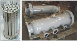
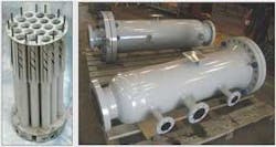
Demister units for Milne Point were engineered and fabricated by ProSep Technologies. Each demister consists of an 18-in. external pipe shell that houses a bundle of 19 axial flow cyclones (2-in. diameter) designed and manufactured by ConSepT. Fig. 1 shows a typical cyclone bundle, alongside one of the fully assembled demisters purchased for the Milne Point facility.
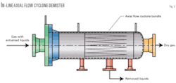
These demisters, fabricated entirely of piping components, are not subject to pressure vessel codes. The cyclone bundles are made of stainless steel to prevent corrosion and are permanently secured to the interior of the demister shell. Fig. 2 shows a view of demister operation.
Gas enters the shell and is evenly distributed over the flow area of the cyclone bundle. Each of the 19 cyclones consists of a tube with a stationary swirl element at the entrance to induce cyclonic motion.
Upon entering each cyclone, gas and entrained liquids begin rotating. Centrifugal motion slings the heavier liquids to the cyclone walls. At the end of each cyclone, a slit in the cyclone wall allows liquids to escape and flow into a nozzle in the bottom center of the shell.
Dry gas from each cyclone combines and exits the shell. Liquids from each cyclone flow downward into a separate level-controlled liquid collection boot (not shown) located a few feet away from the demister. Liquids from each of the four collection boots are tied into the same drain lines that remove liquids from their respective upstream suction scrubbers.
ConSepT performed engineering calculations and computational fluid dynamic simulations of these demisters under Big A/B operating conditions. Results indicated more than 99% liquid removal efficiency over a wide range of inlet liquid loading. The impact of pressure pulsations from the suction bottles was also analyzed and found not to be a factor in demister performance.
Heat tracing, insulation
After installation of the inline demisters, heat tracing will be installed on the four Big A/B suction bottles on the Nos. 1 and 2 cylinders and on the short pipe segments between the bottles and demisters.
The pipe segments will then be insulated, and insulating blankets will be wrapped around the suction bottles. This heat tracing and insulation will prevent any condensation of liquids downstream of the demisters to provide clean, dry gas to the compressor cylinders.
On line monitoring
One of the recommendations made for continuous assurance of Big A/B mechanical integrity was to install on line compressor monitoring and data collection systems. Lack of sufficient, relevant historical data often prevents exact determination of the root cause of a machine failure.
A separate project was initiated to install Prognost and Kongsberg systems, which now provide continuous, real-time data to monitor compressor process temperatures, bearing and cylinder liner temperatures, process pressures, vibration, rotational speed, rod position, and lube-oil system performance.
These robust systems provide numerous alarms of impending or actual machine damage. Potential problems related to liquids ingestion are readily detected, but this is only a small part of the capability of these systems.
Project lessons
Following are major conclusions from this series of three articles:
1. Changing process conditions can significantly increase the potential for damage to a reciprocating compressor related to liquids ingestion.
This can occur as a result of changing liquid and gas production profiles, expansion to an existing facility, or modifications to an existing compressor or related process equipment.
2. The most current tools available should be used to evaluate existing or new compression systems when a potential for liquids ingestion exists. Computational fluid dynamic modeling can identify limitations within existing separation equipment and predict performance of new or retrofitted separators.
On line laser isokinetic sampling probe testing can quantify liquid carryover from existing separators and monitor changes in performance over time. Branch connections for LISP testing should be considered for all new separator vapor lines that feed downstream compressors.
The process systems standard adopted by the Norwegian oil industry requires such connections for offshore production facilities.
3. The impact of NGL solubility in lube oil should be considered when selecting a cylinder lubricant or considering a change to an existing lubricant. Synthetic lubricants should not be viewed as the solution to an ongoing liquid ingestion problem, but may be beneficial in minimizing negative impacts from low levels of liquid entrainment in compressor suction streams.
4. The state of the art in separator technology has improved over the last couple of decades. Before a decision is made on a course of action to address a specific separation problem, a little research into the capabilities of various separation vendors will go a long way to ensuring that a workable solution will be found.
Different companies have different areas of expertise, and a solution from one vendor may work superbly in one situation but not quite so well in another.
5. An on line compressor monitoring system can pay for itself many times over during the life of a reciprocating compressor installation. With immediate access to current and historical compressor data, impending failures can be avoided, downtime can be minimized, and routine maintenance can be optimized.
Various high quality systems are available and in use at reciprocating compressor installations all over the world.


