California line beats odds, begins moving viscous crude oil
Years of environmental review, political battles, and difficult construction culminated in 1999 with completion and start-up of the Pacific Pipeline System in southern California.
The pipeline was designed by Rooney Engineering Inc., Englewood, Colo., which also coordinated permitting and provided construction management. It is owned and operated by Pacific Pipeline System LLC, Long Beach, Calif., a joint venture of a subsidiary Anschutz Co., Denver, and ARCO Pipe Line Co., Houston.
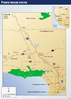
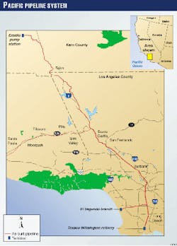
The 20-in. insulated line is transporting Outer Continental Shelf and San Joaquin Valley crude from Emidio, approximately 30 miles south of Bakersfield, to refineries near Los Angeles (Fig. 1). The 130-mile pipeline was designed for 130,000 b/d of the heavy viscous crude, indigenous to the area, in a heated, "neat" form to major refiners in Wilmington and El Segundo.
Pacific Pipeline is connected to such key area pipelines as All American and Equilon's diverse gathering systems in the southern San Joaquin Valley. To be transported by pipeline economically, these crude oils must be heated. Temperatures in the pipeline vary from ambient to 180° F. Pressures in the pipeline vary from 50 to 1,460 psi.
Hurdles
Completion of the pipeline system required clearing numerous permitting, design, and safety hurdles. Some of the more challenging were:
- Intense permitting and agency oversight during design and construction.
- Joint federal and state environmental review producing an exhaustive environmental impact statement (EIS) and environmental impact report (EIR).
- Difficult alignment consisting of a mix of agricultural lands, rugged mountains, and very dense urban and industrial areas. The pipeline traverses the heart of Los Angeles.
- Extraordinary system safety design, including leak-detection capabilities higher than industry norm.
- Detailed hazardous operations analyses.
- Seismic design to mitigate the risk of crossing more than eight major faults, including the San Andreas Fault.
- Stresses from expansion-contraction of thermal cycles caused by a wide operating temperature range.
The challenges were met with the following innovations:
- Horizontal directional drilling of 10 crossings totaling more than 5 miles under active landslides, high scour rivers, and some of the busiest highways in the US.
- Thirty three nitrogen-actuated block valve sites (aboveground and buried) for emergency isolation of the system.
- High-speed, fiberoptic communication and control system.
- Advanced supervisory control and data acquisition (SCADA) system with integrated leak detection and dynamic on-line training simulation.
- Variable-frequency drive for efficient pump operations.
- High-efficiency electrical pump motors and substation equipment.
- Fully functioning backup control center.
- Multichannel, peer-to-peer, Ethernet-based communications between facility programmable logic controllers (PLC)s.
- Sump tanks with secondary containment and continuous leak monitoring.
- Advanced automation-sequence programming and control algorithms.
- Geographic information systems (GIS) mapping and global positioning system (GPS) data collection.
Permitting
To construct the pipeline, PPS obtained permits from more than 50 public agencies, including the California Public Utility Commission (CPUC), US Forest Service (USFS), the City of Los Angeles, Los Angeles County, Kern County, the Metropolitan Transit Authority (MTA), the Los Angeles Department of Water and Power (LADWP), Caltrans, the ports of Los Angeles and Long Beach.
In 1994, PPS formally applied to the CPUC and the USFS for regulatory approval of the route. The USFS and CPUC, as lead agencies, employed an environmental consultant to conduct a thorough environmental review.
Several route assessment and alternative studies were conducted to satisfy the requirements of the National Environmental Policy Act and the California Environmental Quality Act.
In 1996, after successfully completing all of the required assessments, the CPUC and the USFS issued a joint EIR-EIS for the construction of Pacific Pipeline System.
The EIR-EIS reached approximately 3,000 pages and included hundreds of specific measures to be implemented during construction and operation to mitigate potential impacts.
After approval of the EIR-EIS by the lead agencies, final design of the pipeline corridor was completed and plans were submitted to the state and local municipalities for construction permits.
Construction on the pipeline began in June 1997.
Unique alignment
The pipeline was broken into five construction segments, with one segment consisting primarily of agricultural construction, one of primarily mountain construction, and three of primarily dense-urban construction.
Origination; Tejon areas
The line originates adjacent the Texaco Trading & Transportation (now Equilon pipelines) tank farm at Emidio (elevation 425 ft). It tracks southeast 15 miles while gaining approximately 1,400 ft in elevation to the second pump station near the Grapevine interchange of Interstate 5 (I-5; elevation 1,776 ft).
This region is heavily cultivated farmland with row crops, cotton, and grape vineyards.
All of the transportation rights-of-way converge south of Pacific's Grapevine station where the route follows a restrictive corridor known as the "Tejon Bench," with clearances of less than 2 ft from existing utilities. Here, the right-of-way is in places no wider than 15 ft.
The Tejon Bench, which is near eight lanes of I-5, contains two 26-in. gas pipelines, one 16-in. and one 10-in. crude oil pipelines, one 6-in. fiberoptic conduit, and one 4-in. water line.
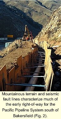
After leaving the Tejon Bench area, the pipeline climbs to a maximum elevation of 4,080 ft at the top of Tejon Pass. This section of pipeline crosses the San Andreas Fault in several locations.
The pipeline then snakes through the rough mountainous terrain of the Angeles National Forest with elevation changes at Liebre Gulch of 900 ft in a distance of 0.5 mile with grades exceeding 50%. In some areas, tracked equipment required the assistance of winches and multiple, tandem bulldozers to scale the steep terrain.
After leaving the forest, the route drops into the Los Angeles basin.
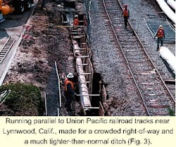
The 55-mile leg through the San Fernando Valley followed congested city street and railroad rights-of-way. Nearly all of the 26 miles of the pipeline in the valley traversed railroad right-of-way.
The right-of-way was congested with industrial and passenger trains, several major fiberoptic lines, a half dozen bridge crossings, and hundreds of cross utilities.
Downtown Los Angeles
This section follows one of the oldest and busiest corridors in the Los Angeles basin along Alameda St. through the heart of downtown. It was built entirely at night because of traffic.
Care was required to preserve historical artifacts uncovered in the course of construction. Pacific employed teams of paleontologists, Native Americans, biologists, and other cultural and environmental specialists to ensure minimal impact during the course of construction.
The pipeline continues south along the Alameda Corridor to several refineries in the Wilmington area.
The pipeline had to avoid the proposed Alameda Corridor project, an ongoing project to build a subsurface rail system between Los Angeles and Long Beach and destinations north.
Track will be laid in a 10-mile by 40-ft deep by 50-ft wide concrete trench with at-grade crossings for the vehicular traffic. During pipeline construction, ongoing design of the Alameda Corridor Project added uncertainty to the space restrictions from the existing utilities.
Near Lynwood, just north of I-105 (Century Freeway), Pacific Pipeline splits, with a second leg paralleling the Union Pacific railroad corridor to Chevron's El Segundo refinery.
Drilled crossings
Construction on this 10-mile route is a mix of street and railroad right-of-way with numerous subsurface obstructions and one of the most difficult directional drills on the project.
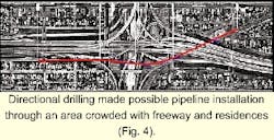
Directional drilling all along the pipeline route made passage possible where congestion or unsuitable surface conditions made traditional construction impossible. The line includes nearly 5 miles of horizontal directionally drilled (HDD) crossings in 10 separate drills.
HDD allowed the line to pass below an active landslide, under three rivers, and under three Interstate highways. Of particular note was a 1-mile crossing beneath the toe of the Gorman Landslide.
But the most remarkable bore was 4,173 ft long and 150 ft deep beneath the intersection of I-105 and I-110 freeways (Fig. 4). Michels Directional Drilling, Brownsville, Wis., completed this drill along with seven others; ARB Inc., Paramount, Calif., completed the other two.
Hydraulics; coatings
The high viscosity and strong temperature dependence of the crude oils transported by Pacific Pipeline required computer models to account for temperature losses in the flowing pipeline.
San Joaquin Valley crude oil ranges in viscosity from 17,750 cst at 60° F. to 1,320 cst at 100° F. and has a gravity of 13.2° API. Its originating temperature is 180° F.
The pipeline was designed to transport crude oils of widely varying ambient temperatures, but with high vapor pressures, heating these oils could adversely affect system performance.
Other products are quite heavy and viscous. Cooling of these oils can make them too viscous to be pumped.
Line pipe coating for conventional construction consisted of a minimum of the following:
- 16 mils of Nap-Guard 7-2501 fusion-bonded epoxy (FBE).
- 2 in. of urethane foam for insulation.
- 20 mils of polyethylene tape as binder.
- 75 mils of extruded polyethylene jacket for abrasion and ultraviolet resistance.
The pipe was coated with an additional 1-in. concrete at all road and railroad crossings. Coating for the HDD crossings omitted urethane insulation, tape, and polyethylene jacket.
To maximize the abrasion resistance and protect the cathodic coating, the directional drill composite coating consisted of 27 mils of FBE (9 mils of primer coat Nap-Guard 7-2501 and 18 mils of top coat Nap-Guard 7-2504 FBE) and 75 mils of Powercrete for mechanical abrasion.
Physical properties of the urethane foam and the extruded polyethylene jacket were specified for low weight, minimizing heat loss, maximizing service life, and mechanical strength required for installation process.
Key specifications were the following:
- Core density of 2.75-3.00 lb/cu ft.
- Average compressive strength of 50 psi.
- Shear strength of 35 psi.
- Open-cell content of 10% maximum.
- Water absorption of 20% by weight, maximum
- Thermal conductivity 0.145 btu-in./hr-sq ft-°F. maximum.
Bredero Price, Fontana, Calif., coated the line pipe. The urethane foam consisted of two parts isocyanide (Part A) and hydrogen chlorinated fluorocarbon blowing agent (Part B).
Parts A and B were transferred from storage containers into separate ration pump reserves and heated between 100 and 145° F. for mixing. Ration pumps transferred the individual components through heated transfer hoses to the application nozzle.
A multiple gun arrangement sprayed the foam insulation onto the line pipe turning longitudinally in a single pass to a 2-in. foam thickness. A 20-mil polyethylene tape was mechanically applied under tension and over the foam insulation. A 75-mil extruded polyethylene outer jacket was then applied by side extrusion and pressed directly into the polyethylene tape.
The color of the outer jacket was white in order to minimize expansion and contraction of the polyethylene jacket and to protect it from exposure to ultraviolet rays while the coated pipe was stock piled for several months.
Line pipe
American Steel Pipe, Birmingham, Ala., manufactured the line pipe to API 5L specifications in quadruple random lengths, except for approximately 20 miles in the rugged forest terrain. For there, the pipe was provided in triple random lengths.
The pipe was delivered via rail to Bredero Price's facilities in Fontana.
In the field, each weld was X-rayed and certified in compliance with API 1104. Induction coils were used for a field application of 25 mils of Nap-Guard 7-2501 in the girth weld area.
Urethane foam insulation (half-shells) was then installed on top of the FBE coating, followed by Raychem or Canusa heat-shrink sleeves to keep water from migrating into the urethane foam.
IPEC shrink sleeves were installed at every third or fourth field joint to eliminate the migration of water from one joint to the other.
Casing pipe for the bored crossings was specified at 0.625-in. WT. Bores at all major Interstate and railroad crossings were cased.
Pipeline cover was 36 in. for US Forestry Service lands, 48 in. for paved roads, and 60 in. on railroad right-of-way.
The Pacific system was designed to accommodate smart pigs. Fittings of three times pipe radius (3R) were used throughout the project. A 20-in. launcher was installed at the Emidio pump station, and a 20-in. receiver was installed 119 miles away at Wilmington.
A 20-in. launcher was also installed at the Lynwood Junction facility on the El Segundo branch, with a receiver at the El Segundo refinery.
Several factors dictated maximum operating pressure, including the need to meet or exceed requirements of the US Department of Transportation and California State Fire Marshal.
Determining maximum operating pressure considered the specified minimum yield strength (SMYS) for the pipe components, temperature effects on flange and fitting ratings, and maximum stress to which the pipe was subjected during hydrostatic testing.
The WT and grade of the majority of the 20-in. line pipe was 0.312-in. ERW, Grade X-65. Pipe of heavier wall thickness (0.500 in.) was used in seismic, landslide, road crossings (cased or slick bores), stream crossings, and all HDD crossings.
Various safety factors (SF) were used in design; US 49 CFR 195 required some, and others were additional safety factors. (CFR = Code of Federal Regulations)
These latter were 0.72 in nonrailroad areas and 0.60 in railroad rights-of-way. Based on the WT and safety factors, the maximum pressures were calculated as 1,460 psi (SF = 0.72 and 0.312-in. WT) and 1,217 psi (SF = 0.60 and 0.312-in. WT).
The flanges selected for the line were primarily 600-lb ANSI, rated at 1,440 psi at less than 100° F.
Since the pipeline operates at temperatures of 180° F., a design temperature of 200° F. was selected as the upper end. At this temperature, the 600-lb ANSI flanges had to be de-rated to 1,350 psi to account for the temperature effects.
The rugged terrain through the Angeles National Forest and numerous elevation differentials complicated selection of the hydrostatic test sections.
Pressurizing the pipe at the top of the mountains high enough to qualify for high operating pressures without over pressurizing the line at the lowest elevation in the same hydrostatic test segment required a large number of "stair-cased" segments.
Valves
The project includes 33 nitrogen-actuated block valves along the 130-mile route.
The known earthquake potential in southern California dictated use of nitrogen actuators, with the concern for simultaneous disruption electrical power. These valves allow Pacific, in a loss of power, to isolate the pipeline and maintain control.
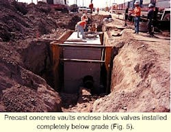
Block valves (9) in such rural areas as the Forest Service are aboveground. In urban areas and railroad rights-of-way, the remaining 24 block valves were completely buried in precast concrete vaults. These have manhole-access covers and are traffic rated since many are installed in roadways.
Pressure and temperature sensors, also at each block-valve site, are tied directly into the SCADA system and provide data for the leak-detection model. Pressure is monitored via taps both upstream and downstream of the valve.
In addition to the block valves, the pipeline has 20 full-port check valves placed to limit back flow in a line break. Of the 20, 11 are in rural areas and aboveground. The remaining 9 are in buried vaults similar to those used for the block valves.
Communication
Backbone of the SCADA control system is a high-speed fiberoptic-based communication network. The fiber-optic duct, installed in the trench along with the new pipeline, allowed for 12 operational fiber strands.
The 54 megabit/sec OC-1 fiber protocol allows for not only SCADA data transfer, but also live video feed from each of the stations.
The actual realized scan rate for the system is 0.25 sec for critical leak-detection model data and 1 sec for all other data. Rooney Engineering developed "Valid Flow Path Determination."
The MODTCP protocol allows for PLCs to exchange data efficiently with each other in a peer-to-peer format. The net effect is that PLCs can communicate critical data to each other without sending it to the host, while being polled by the host.
The Valid Flow Path Determination feature takes advantage of the multichannel, peer-to-peer communication capabilities to verify that an open path (no closed valves) exists from delivery to the pipeline origin. Valve status and other critical monitoring information are passed upstream from PLC to PLC from the delivery location to the originating pump stations.
If any valve in the entire system starts to close, this information is propagated up the pipeline to the originating pump stations. The pumps are automatically stopped and the pipeline brought to a low-energy state before the valve is even partially closed.
Leak detection
The pipeline is operated from a control center in Long Beach where the SCADA system has a fully configured, redundant, hot standby system. In addition, a fully redundant, cold standby backup-control center is at the Emidio pump station.
The SCADA system selected for the pipeline was developed by GSE, Concord, Md. (now a subsidiary of Neles Automation, Calgary). The software combines the supervisory and simulation functions in a fully integrated system operating on a Windows NT platform.
The integrated S-3/SCADA and leak-detection packages allow for seamless data transfer between the supervisory and leak-detection applications. These functions share common databases used by the data acquisition, simulation, leak detection, operator training, and other advanced application modules.
This level of integration reduces the potential for programming error, overall programming time, and data-exchange times required for moving raw data between applications resulting in a more robust and reliable operation.
Advanced leak-detection capabilities are made possible by a high-speed hydraulics model running with a time step of 0.25 sec. The model converges to a mathematical solution of the pipeline operating conditions four times/sec. This corresponds to the data-acquisition rate from the SCADA system.
This model simulates the dynamic behavior of the pipeline using the mathematical technique known as "Method of Characteristics." The results from the mathematical solution are then compared to the "real world" data received from the field in search of deviations indicative of a leak.
The leak-detection system displays the results of the model pressures, etc., on a graphic display of the pipeline showing the ground profile, hydraulic gradient, and maximum operating pressure of the pipeline. This hybrid graphical display also includes "real-time" data such as pump run status, all pipeline pressures, and other critical information for safe operation of the pipeline.
The same model that calculates hydraulic data for the leak-detection model comparison with live field data also provides the backbone for an advanced operator training system.
In addition to providing hydraulic data for training purposes, the training system also simulates the end devices such as valves and pumps along with simulation of the operator interface screens.
One final item was required to make the training system look and act like the real system. The local PLC or controller is often overlooked in the development of training systems because the amount of programming required accurately to emulate the PLC is usually prohibitive.
In the case of the Pacific system, however, the PLCs were programmed with function block language instead of the typical ladder logic. This made it simple to translate the PLC language directly to a format that is executable by the simulator.
Thus, the simulator includes all of the alarms, PID control settings, and other control operations of the PLC in the field. As a result, the training simulator looks, responds, and controls in exactly as the real system.
Station design
The pipeline includes two pump stations, one pressure-reduction station, three metering and delivery stations, and one scraper and valve facility. Also included are a variable-frequency drive and automated scraper passing piping.
The Emidio station is the originating pump station and sits adjacent Equilon's tank farm approximately 30 miles south of Bakersfield. Some of the major components located at this facility include:
- Shop and office building housing the backup control center.
- Seismic monitoring and ESD sensors.
- Meter skid with three 10-in. meters.
- Stationary, bi-directional, 16-in. barrel ball-prover with four-way valve.
- Flow-control valve for metering system.
- Mainline pump skids: Three horizontal split case centrifugal pumps piped in parallel (2,489 ft discharge head each).
- Three 2,000-hp electrical motor pump drivers.
The Grapevine station is the intermediate pump station and is on Tejon Ranch at the foot of Grapevine Pass, approximately 15 miles south of Emidio station on I-5.
Some of the major components at this facility include seismic monitoring and ESD sensors; mainline pump skids (three horizontal split case centrifugal pumps piped in series); three 2,000-hp electrical motor pump drivers; and a variable-frequency drive.
The Whitaker pressure-reduction station is on a remote portion of Angeles National Forest. It removes the extra hydrostatic pressure gained by the elevation differences between Tejon Pass (4,080 ft) and the terminus of the pipeline (sea level).
These pressure-reduction valves remove up to 1,000 hp from the flowing stream. Some of the major components at this facility include automated pig passing and severe-service throttling valves, two piped in series.
The Lynwood Junction station diverts flow either south toward Wilmington station or west to El Segundo station. The stream can also be split between them both simultaneously.
This station sits in the heart of south central Los Angeles, approximately 107 miles from Emidio station. Permit requirements dictated that this aboveground facility be secured by a wall that, from the outside, appears to be a building.
The Wilmington delivery station delivers to the Equilon (Texaco), TOSCO, and Huntway refineries in the Wilmington area. The El Segundo Delivery Station delivers to the Chevron refinery in the El Segundo area.
And the bi-directional EPTC delivery station delivers to and receives crude oil from the Edison Pipeline and Terminal Co. (EPTC) facility at Dominguez Hills.
Construction; line fill
The pipeline project was bid to nine union contractors and divided into five segments.
ARB was awarded Segments 1, 2, 3, and 5, for a total of 110 miles, and Hood Corp., Whittier, Calif., received Segment 4 for 20 miles.
SII, Valencia, Calif., completed Emidio, Grapevine, Whitaker and Wilmington stations. ARB Inc. completed Lynwood and El Segundo stations.
Scott Co. of Gardena, Calif., constructed the EPTC station.
The rugged terrain prompted Pacific to fill the pipeline from both ends toward the high point at Tejon Pass. To accomplish this, crude oil was transported to the Chevron refinery in El Segundo and stored in tanks.
Light crude oil was used because of the slow pumping rates and potential time delays that would result from the cooling of heated, heavy crude oil. Pumping rate for line fill varied from 1,000 bbl/hr to 2,000 bbl/hr.
Halliburton was contracted to provide positive-displacement pumping equipment and perform pumping labor and oversight. One set of pumps was set up at the Chevron refinery and another installed at Hugh's Road block valve (immediately south of Whitaker station).
These two temporary pump stations were capable of lifting crude oil to the top of Tejon Pass with nearly 4,000 ft of elevation change. Ahead of the crude oil, a series of neoprene pigs was launched followed by approximately 40 miles of nitrogen to purge the pipeline of air. After the nitrogen, another series of pigs was launched as a buffer between the crude oil and the nitrogen.
The pigs allowed the pipeline to be filled and maintain line pack. To fill the line, the pigs had to travel upstream. The exterior mechanical arm lifted the clappers in the check valves so that they could be pinned out of the flow.
Pig indicators installed at the block valves tracked the progress of the fill. Vent piping was installed at Tejon Pass. Once nitrogen was detected at the summit, vacuum trucks hooked up to the vent piping prevented oil from being released.
After the line was filled from the south end to the top of Tejon Pass, the Halliburton pumps were moved to the Emidio and Grapevine stations. The north end of the line was filled with OCS crude oil because it could be pumped at ambient temperature.
The pigs and nitrogen were transported through the pipeline to the top of Tejon Pass where the line was again vented. Line fill for the pipeline was completed in approximately 10 days.
Start-up
During line fill of the northern portion, preliminary tests were made at the delivery facilities using static head provided by the oil from the completed line fill operations.
These threshold flow tests started at the Wilmington delivery facility and were designed to test the capabilities of the pressure-reduction control valves and verify the overall performance of the control system at each facility.
As a result of extensive simulation and testing before commissioning, both Wilmington and El Segundo were verified as operational within design parameters in 2 days. Completion of these verification tests coincided with completion of line fill on the northern portion.
Before the Halliburton pumps were removed from Emidio and Grapevine, threshold testing was completed at Whitaker station. During these tests, capabilities of the pressure-reduction valves and performance of the control system were verified.
Again, the verification tests were completed in 1 day.
With operation of the downstream control system verified, attention focused on the pump stations.
Starting at Emidio, pumps were started and operated briefly. Two days later, both Emidio and Grapevine were started with operations commencing in February 1999. Heated transportation began in March 1999.
Acknowledgment
The management of Pacific Pipeline, led by Douglas L. Polson, chairman, and Irvin Toole Jr., president and CEO, helped resolve critical issues during construction.
The Authors
Dean Shauers is president of Rooney Engineering Inc., Englewood, Colo., which he joined in 1988. Before joining Rooney, he worked for Marathon Pipeline for 10 years in various project-engineering capacities.
Shauers holds a BS (1979) in civil engineering from the University of Wyoming.
Henrick Sarkissian is senior project manager at Rooney, joining in 1992. He holds a BS (1979) in petroleum engineering from the University of Tulsa.
Bill Decker is a senior project manager at Rooney, joining in 1996. Before coming to Rooney, he worked for Texaco Trading & Transportation Inc., Getty Oil, and Continental Pipeline Co. (Conoco). He holds a BS (1979) from Colorado State University, Fort Collins, in industrial construction management.
Travis Mecham is the regional manager for Rooney in Tulsa and holds a BS in electrical engineering from the University of Missouri-Rolla.
Bruce Wilkerson joined Rooney in 1995 as a senior project engineer in Communications and Automation. He holds a BS (1985) in mechanical engineering from Utah State University, Logan.
