Storage-tank leak detection improved with cable-sensor system
Based on a presentation to the 19th Annual ILTA International Operating Conference, Houston, June 14-17, 1999.
Since 1995, Kinder Morgan Energy Partners LP, Orange, Calif., has used a cable-sensor system to improve leak detection from its aboveground storage tanks.
The company now has 67 tanks and 14 valves under continuous monitoring by the cable sensor leak-detection system. These systems have been installed at 25-50% the cost of alternate technologies and have incurred minimum maintenance and troubleshooting costs.
After soil studies in 1995 led Kinder Morgan to conclude a more responsive form of leak detection for aboveground storage tanks was needed, the company evaluated several leak-detection technologies before selecting the noncentralized cable sensor system. The system is installed with horizontally drilled leak sensor pipes.
One main compromise a user must accept in selecting the cable-sensor technology is that it cannot be centrally monitored. Leaks are indicated by aboveground flasher units that must be observed by an operator on a tank farm inspection.
The advantage of this compromise is that power and signal conduits to a central location are not required, and overall installation and follow-on costs can be significantly less than other available technologies, allowing more tanks to be monitored for the same investment.
The cable sensor system is simple in operation and provides good redundancy because each of the two or more flasher units at each tank is a standalone leak-detection system.
System need
Kinder Morgan has several hundred aboveground storage tanks in service in the US Midwest and West. Although there is an ongoing program to inspect, repair, and protect all of the tanks from conditions that could cause a leak, there are always unknown conditions that can initiate a leak without warning.
Time is the enemy in a slow-leak scenario because of the vertical migration that occurs. Cleanup costs and out-of-service time expand geometrically as the depth of vertical migration increases.
For these reasons, Kinder Morgan decided that a more responsive leak-detection method should be pursued.
To define leakage migration rates, Kinder Morgan in 1995 authorized a soils-engineering firm to take soil samples and perform detailed permeability studies at a California terminal. The terminal was representative of the tank-foundation designs that have been used throughout the company for many years.
This typical foundation design includes a 3-ft layer of recompacted native or imported clay-laiden material, followed by a 1-ft layer of 3/4-in. gravel (road-base material), followed by a 3-in. layer of oiled sand upon which the tank floor plates rest.
A concrete ring wall is typically not used in the foundation design.
The study included taking core samples through the outer edge of several tank foundations, which were subjected to conductivity and total-organic-carbon tests to determine relative permeability for the gravel layer and clay-silt layer.
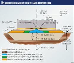
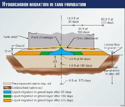
A hypothetical small 1-gal/hr gasoline leak was defined for study from the center of a small (25-ft diameter) tank and a large (125-ft diameter) tank. The study concluded that the leak would travel in the underlying gravel layer horizontally for a distance of 14.3 ft in 30 days, 35 ft in 180 days, and 62.5 ft in 575 days (Fig. 1).
This hypothetical leak could be visible at the outer edge of a small tank in 1 month but would not be visible on a large tank for more than 11/2 years. At the same time, the same leak scenario could cause vertical migration into the underlying clay-silt layer of 0.3 ft in 30 days, 1.9 ft in 180 days, and 6 ft in 575 days.
This study helped to confirm that the gravel-over-clay layering foundation design is a good approach for limiting vertical migration. The study was useful in defining a preferred location for leak-sensor pipes that needed to be installed under tanks for leak sensing.
It was determined that perforated (screened) leak-sensor piping should be located at the base of the gravel layer and no more than 30 ft apart. That is, a leak will need to travel no more than 15 ft before it reaches a sensor pipe.
Evaluating technologies
Before installing any leak-detection system, Kinder Morgan evaluated five technologies available in 1996. All would provide a continuous monitoring of perforated pipes installed beneath tanks.
Technologies that provide a periodic or one-time test of tank integrity were not considered because continuous monitoring was mandatory. Following are the technologies evaluated:
- Vapor sniffer. This technology uses a centrally located vapor sniffer that sequentially sniffs long lengths of small-bore tubing that run to the sensor piping under each tank.
- Fiberoptic, vapor-liquid sensor. This technology uses a centrally located electronic box and computer to monitor specially coated fiberoptic sensors located in the sensor piping under each tank.
- Polymer-ribbon sensor. This technology uses a centrally located electronic box to monitor the resistance of special hydrocarbon-sensitive ribbons located in the sensor piping under each tank.
- Coaxial cable, impedance-based sensor. This technology uses a centrally located electronic box to monitor the impedance characteristic change of hydrocarbons soaking into the coaxial cables located in the sensor piping under each tank.
- Cable sensor. This technology uses a local flasher electronic box that monitors the open-closed status of a special hydrocarbon-sensitive cable located in the sensor piping under each tank. Each cable sensor is an independent system with its own battery-powered flasher unit.
Each technology evaluated had advantages, disadvantages, and associated costs, and each appeared to provide various levels of continuous monitoring for the presence of hydrocarbons. To be effective, each technology required the installation of sensing pipes beneath each tank to gain access to tank bottom leaks.
One notable difference in the evaluations was that the cable-sensor technology did not require centralized monitoring because each sensor cable had its own inexpensive battery-operated flasher unit that made it a standalone leak-detection system. Use of this technology would avoid the installation of thousands of ft of conduit and cable for power and signals.
The disadvantage was that leak detection could not be centrally monitored by a supervisory control and data acquisition (SCADA) system. Because each tank farm at a Kinder Morgan site is inspected numerous times daily for problems, it was concluded that the flasher units could be monitored during each walk-through without a manpower impact.
By accepting this monitoring technique, Kinder Morgan was able to realize significant costs savings associated with centralized monitoring that would have been required for other technologies.
Cable-sensor system
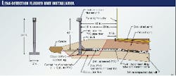
The cable-sensor system consists of a hydrocarbon-sensitive cable connected to a battery-powered electronic flasher module mounted about 3 ft above the tank apron at one end of a 2-in. screened PVC pipe installed beneath the bottom of the tank (Fig. 2).
The hydrocarbon-sensing cable (Fig. 3) is about 1/4 in. in diameter and consists of a set of seven wires twisted together, then covered with a hydrocarbon-sensing polymer, followed by an outer braid.
Two of the wires, called electrodes, are coated with a special conductive polymer that will connect with the outer polymer when activated by hydrocarbons. In the presence of hydrocarbons, the two electrodes act as a switch to activate the flasher module.
Because the outer polymer will swell on contact with hydrocarbons, the outer braid is designed to force the polymer to swell inward to squeeze the two electrode wires tightly together to act as a solid contact closure to the flasher module. The remaining wires in the cable are not used in this application.
After the cable is activated by hydrocarbons, it must be replaced.
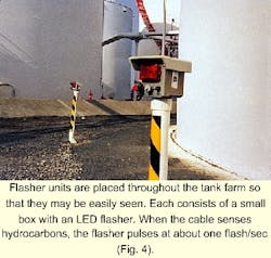
The flasher unit (Fig. 4) consists of a small PVC NEMA 4X box with a strobe-like LED flasher, including compact sealed electronics, two AA alkaline batteries, a "Push-to-Test" button, and a vapor-sampling port. When the cable senses hydrocarbons, the flasher will pulse at about one flash/sec.
The unit includes internal sensing circuitry to detect a "low battery" condition that will operate the flasher at a different pulse rate. The manufacturer claims the batteries will operate the unit for 2 years but recommends replacement of batteries annually. The batteries are designed to operate the flasher continuously for up to 2 weeks after being activated by hydrocarbon detection.
The 3-v power source makes the unit safe for operation in NEC Class 1, Division 2 locations, as is typically the case in a tank farm. The vapor-sampling port on the unit is attached to a 3/8-in. tube that extends for several ft under the tank to provide a quick sniffer verification of a leak condition after the flasher alarm goes off.
Installation
All tank leak-detection technologies require some way to get under the tank so that bottom leaks can be detected. Kinder Morgan has chosen to use 2-in. screened PVC pipe rather than a smaller size because it allows any available leak-detection technology to be used and will double as an insertion path for a cathodic protection reference cell when needed.
The screened pipe is basically Schedule-40, white PVC pipe with 20-mil slots cut laterally around the pipe every 1/4 in. Additionally, the pipe ends are threaded into each adjacent section to form a smooth coupling to simplify pulling the pipe into the 2-in. bored hole.
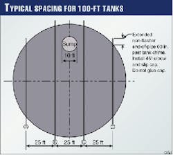
The screened PVC pipe is usually installed in a parallel configuration (Fig. 5) with the pipe extending beyond the tank shell by 3-5 ft on each side. The target depth is 12-15 in. below the bottom at the outer shell.
For cone-up tank bottoms, the pipe can be installed level across the tank. For cone-down tank bottoms, the drill operator has the challenge of maintaining the bit approximately 12-15 in. from the tank bottom based on design information about how the bottom was originally built.
The location of the bottom sump must always be defined and accommodated because the sump usually extends below the level of the drilling.
Drilling methods
Kinder Morgan has used both impact and rotary methods of horizontal drilling for installation of the 2-in. screened PVC pipe.
The impact method uses an air-driven hammering mechanism to drive the drill rod and bit through the tank-foundation material.
This method uses a wedge-shaped bit that includes a differential-pressure sensor in the bit head to determine depth for guidance purposes. The elevation of the bit is controlled by rotation of the wedge from the up to down direction and vise versa.
Control in the vertical direction is very good (plus or minus 1 in.). Control of drift in the lateral direction is limited and can be 1-2 ft away from the target when it reaches the far side of the tank. This method pulls the PVC pipe into the borehole behind the bit as it inches forward.
The impact method is relatively slow and labor intensive (not automated), and it is about as noisy as a jackhammer. This boring method has an advantage that it is operated completely dry; no water is needed to assist or cool the bit. This leaves the screened PVC pipe fairly clean and ready to accept a sensor cable as soon as the bit and drill rod are removed.
The rotary method uses a commercially available horizontal drilling rig with semi-automated features. It uses a wedge-shaped bit that has an angle-of-tilt sensor in the bit head that is remotely monitored at the drill rig console.
The drill rig pushes as it rotates the bit for about 1 ft then stops, and the angle-of-tilt is checked. If correction is needed, the wedge is turned slowly to an up or down position and is pushed for a few inches without rotation then is checked for angle-of-tilt again, and the cycle is repeated.
This method uses a bit-locating transmitter box placed on the opposite side of the tank. The locator box also is used to indicate the distance of the bit from the box and to allow for correction of lateral drift.
The rotary method uses a high-pressure water stream in the bit to assist and cool the bit action. This causes the borehole and lead-in trench to fill with mud from the drilling operation, but the small amount of mud created rarely requires special handling or removal.
After the drill bit exits at the far side, a swivel pulling head is installed to pull the screened PVC pipe back into the bore hole as the drill rods are pulled back toward the drilling rig.
For new tank installations, Kinder Morgan completes the tank foundation up to the compacted gravel base, then uses a trencher to dig down to the base of the gravel to lay in the 2-in. screened PVC pipe. After the PVC is installed, the trench is then back filled with gravel and compacted.
Attempting to install the PVC pipe before the gravel layer is placed has caused construction problems because of the vulnerability of the PVC under heavy construction equipment.
The PVC pipe is typically extended 3-5 ft outside of the tank shell where a 45° coupling is attached followed by a short length of PVC pipe and a slip-on cap. Because protection of the PVC pipe ends poses a problem, it is recommended to end the pipe below grade and mark it with a stake so that the ends will not be damaged during tank construction.
Costs
For estimating purposes, it should be assumed that two sensor pipes will be required for tanks up to 60 ft in diameter, three for tanks up to 90 ft, and four for tanks up to 120 ft. Drilling and installation of 2-in. PVC pipe under existing tanks has typically cost $30-40/ft of installed pipe. Sensor cable typically costs $13/ft.
The flasher units typically cost $1,800 each. Installation of the sensor cable and flasher unit have cost $500/unit; engineering and construction management, typically $30,000-50,000/project (for 20 or more tanks).
All of this translates to a cost of $10,000-35,000/tank. For example, the cost for retrofitting leak detection on a 55-ft diameter tank would be approximately $12,000; for a 110-ft diameter tank, approximately $30,000.
Although Kinder Morgan has no specific construction-cost data on alternate technologies to compare to costs for the sensor-cable systems, preliminary cost studies indicated the costs would be 50% to 100% higher for the alternate technologies.
For some technologies, the cost of sensors and electronics was a major part of the cost difference, but for essentially all of the alternate technologies that involved a central monitoring point, the cost of trenching, conduit, and cable from the tanks to the centralized monitoring location increased significantly the cost differential.
Costs listed above are for first-time installation; other costs related to leak-detection systems are for maintenance, including calibration, sensor cleaning, and battery replacement.
Unanticipated but sometimes significant costs can result from false alarms generated by leak-detection systems. These costs are usually man-hour costs associated with investigations, reporting paperwork, laboratory work, and tank inspections.
With the cable-sensor system in use by Kinder Morgan, there has been minimum maintenance, consisting primarily of annual battery replacement. The rather low-tech system does not require calibration or sensor cleaning and has resulted in essentially no false alarms.
Analysis of other leak-detection technologies has indicated that some have had hardware failures, some need frequent calibration and sensor cleaning, and some have frequent false alarms.
Experiences, problems
At Kinder Morgan, cable-type sensors have been installed on 67 tanks to date at eight different sites, plus monitoring of 14 underground valves. Current plans include installation of this type system on a number of additional tanks.
As a result of the implementation of these leak-detection systems, the following experiences and tips are offered:
- Drill-rig space requirement. Both impact and rotary drilling rigs will require approximately 20 ft of space in front of each drill hole. Typically, if space is unavailable on one side of the tank, there is adequate space on the opposite side.
- Maintaining drilling distance from tank bottom. Tank bottoms either cone up or cone down. For cone-up bottoms, a flat horizontal drilling path is suggested, but be sure to avoid the sump.
For cone-down bottoms, the drill operator will need to know the degree of bottom slope to maintain a safe distance from the bottom. The designer will need to provide this information from existing tank records.
- To drill through or not. Initially, the Kinder Morgan design did not require exiting the sensor pipes on the opposite side of the tank. The intent was to push the sensor cable into the pipe with an electrician's fish tape or long rod.
Problems arose on several runs where the cable would not slide smoothly. In later installations, the pipes were installed to exit on the far side, and the cable was pulled in without problems or damage.
- Taking soil samples. During early installations, soil samples were taken near the center of each bore. The samples were used to confirm that the bore was still in the gravel layer and not too far into the clay layer.
Sampling was time-consuming and done only to satisfy a regulatory request. Samples were taken with a 1-in. diameter hollow sampler that was driven 18 in. in the direction of the bore and then withdrawn for evaluation.
- Drilling under tanks with existing contamination. If old contamination is found when drilling under a tank, do not abandon hope. The sensor will only activate if there is standing liquid or high vapor concentrations.
Kinder Morgan has successfully installed sensors under tanks where old leaks or spills had occurred several years before. If heavy rains bring water into the tank foundation area, however, an alarm may occur as a result of floating residual hydrocarbons. Generally, old contamination will not activate the sensor.
- Bury or conceal opposite end of sensor pipe. When installing sensor pipes, take care to bury or otherwise protect the far end of each pipe from damage. Experience has shown that any PVC pipe that extends above the tank apron will eventually become damaged.
The suggested approach is to bury the pipe end just below grade or conceal it in a flush-mounted fiberglass irrigation box.
- Caution on use of PVC adhesive. Solvent-type PVC adhesive or the vapors from the adhesive will activate the sensor cable. If any of the adhesive is used for the sensor pipe installation, it must air dry for at least 24 hr before coming in contact with the cable.
- Installation. Care must be used when installing sensor cable to make sure it does not loop or kink. A kink will activate the cable, although it will recover when the kink is removed.
Workers must be careful to clean their hands when handling the cable. Any oil that gets on the cable during installation will likely activate the cable.
- Removing drilling mud. When using the rotary drilling method in which water is used for drill-bit cooling and lubrication, it will be necessary to flush and swab out most of the drilling mud from inside the PVC pipe prior to installation of the sensor cable.
If this is not done, the mud will dry around the cable and make it difficult to remove later. Usually, pulling a rag through the pipe several times will be adequate to solve this problem.
- Typical drilling times. For an 80,000 bbl tank (approximately 100 ft in diameter), the impact drilling method will typically require 6 hr/bore, except where extra-hard soil is encountered. The same bores can be completed in about half that time when rotary drilling is used.
For about 5% of the bores made by Kinder Morgan, extra-hard soil was encountered. For those cases, the time required was three to four times longer. In one case, a rotary rock bit had to be used for part of the bore.
- Monitoring tanks with membranes or double bottoms. Very few tanks in the Kinder Morgan system have external membranes or double bottoms. For these installations, the membrane and the lower bottom were designed with a low spot or sump that is connected to a pipe that extends to one side of the tank.
A single sensor cable was used in each case to monitor the 3-in. pipe for tank leakage.
- Monitoring underground valves and flanges. A significant number of leaks in the Kinder Morgan system have been from underground valves that include flanges and from stand-alone underground flanges.
Leak detection should be provided at all locations where underground flanges are in service. The suggested method is to install a "J" shaped section of 2-in. screened PVC pipe beneath the valve or flange with the flasher box mounted aboveground.
- Monitoring space in double-walled underground tanks. The cable-sensor systems have been used successfully for monitoring the interstitial space between the inner and outer wall of underground storage tanks, such as sump tanks and oil-water separators.
The Author
Rudy S. Hogg is senior project manager for Kinder Morgan Energy Partners LP (formerly Santa Fe Pacific Pipelines) handling multidiscipline construction projects for refined product pipelines, pumping stations, storage facilities, and loading terminals.
He is responsible for all leak-detection installations at storage and terminal facilities in the Pacific operations area of the company. Hogg had early experience in water and power with the US Bureau of Reclamation, followed by experience in SCADA system design with Morrison-Knudsen Engineers. The last 9 years have been in petroleum transportation and storage with Chevron Pipe Line Co. and Kinder Morgan. He holds a BS in electrical engineering from Colorado State University.
