Magnetostrictive sensor technology proven in process applications
Various tests and operating environments have successfully demonstrated magnetostrictive sensor (MsS) technology.
This relatively new technology enables a nondestructive examination (NDE) survey of pipe walls to detect corrosion, erosion, and circumferential cracks.
MsS technology is attractive because it can detect corrosion under insulation without removing all involved insulation and detect corrosion in tubing in situ. Particularly, only insulation where the MsS sensors are placed needs to be removed when corrosion under insulation is suspected.
For tubing, only limited access to ends of the tubing is necessary for inspection by MsS technology.
The distance down the pipe that the MsS wave travels depends on the pipe diameter, wall thickness, amount of general corrosion in the pipe, and type of liquid in the pipe. Generally, the smaller the diameter and the wall thickness, the greater the distance the wave will travel. The distance will be shorter if there is a large amount of general corrosion or in pipes with heavy crude oil.
The technology produces an elastic wave that travels in the wall of the material. It is sensitive to variations in wall thickness or geometry that is greater than a few percent of the total wall cross section in the circumferential direction. MsS can also monitor processes that affect pipe wall geometry, such as corrosion and cracking.
MsS technology can generate and detect time-varying stresses or strains in ferromagnetic materials.
When ferromagnetic materials are placed in a magnetic field, they are mechanically deformed. This phenomenon is the magnetostrictive effect, which was first reported by Joule in 1847.1
The reverse phenomenon, in which the magnetic induction of the material changes when the material is mechanically deformed, is called the inverse magnetostrictive effect. E. Villari discovered this inverse effect in 1864.2
Like the piezoelectric effects, which are used in generating electricity as a result of pressure in a crystalline structure (such as quartz), these phenomena are useful for generating and detecting mechanical stresses, deformations, and oscillations.3
The MsS technique has an advantage over piezoelectric transducers when used in relatively low frequencies (less than several hundred khz). The MsS technique requires no direct physical contact to the structural surface; thus, it requires no coupling medium to get an elastic wave in the material. Also, its conversion efficiency is sufficiently good for practical use, even on ordinary structural steel.
Currently, if technicians set the detection threshold at 5-10% cross-sectional defects (that is, sensitivity to variations of 5-10% of the cross-sectional wall of the pipe), the MsS system provides high detection with a low false call rate.
If the threshold is set for 1% cross-sectional defects, the system provides high detection with a high false call rate. Scientists are currently addressing this issue with signal processing.
Sensor configuration, instrumentation
Each setup of the MsS system takes the technician about 1 hr.
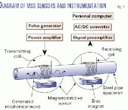
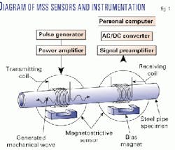
Fig. 1 shows a schematic diagram of the MsS and associated instrumentation for inspection of piping or tubing from the outside diameter (OD). The instrumentation generates and detects elastic waves in ferromagnetic materials.
The MsS consists basically of a coil and a bias magnet. The transmitting coil applies a time-varying magnetic field that generates an elastic wave in the material under inspection (in this case, in a pipe wall) via the magnetostrictive effect.
The receiving coil detects changes in the magnetic induction of the material caused by the elastic wave via the inverse magnetostrictive effect.
A bias magnet provides a DC bias magnetic field to the material. The bias magnet, which can be either a permanent magnet or an electromagnet, is necessary to enhance the efficiency of the MsS and to make the frequencies of the electrical signals and the elastic waves the same.3 Sometimes residual magnetic fields induced in the material can be used as the DC-bias magnetic field.
Application of a short-duration pulse of electric current from a pulse generator and power amplifier activates the transmitting coil. The voltage signals determine the size of the elastic waves detected by sensing voltage signals, which are induced in the receiving coil by the changes in the magnetic induction of the material via the Faraday effect.
The equipment used with the receiving coil includes a signal preamplifier, an AC-to-DC converter, and a personal computer (or a digital oscilloscope).
Detection of corrosion
MsS can generate and detect elastic (or guided) waves. These waves are useful in long-range inspection of ferromagnetic piping and tubing.5-7 Scientists have conducted extensive investigations of the MsS capabilities in laboratories and in the field.
MsS technology has proved useful in pipe and tubing inspection over a wide range of operating conditions, including:
- In both carbon steel and alloy steel materials.
- In pipe or tubing with sizes up to 40 cm in diameter.
- In wall thicknesses up to 3 cm.
- In pipe temperatures up to 455° C.
- In both OD and ID inspection applications.
- In applications in which the sensor is up to 5 cm from the pipe outside surface.
The MsS technique can inspect a long segment of pipe or tubing for detection of isolated internal and external defects, such as corrosion and circumferential cracks. It can also give an assessment of the general condition of the structure.
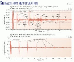
Data in Fig. 2 show the capabilities of the MsS technique.
Fig. 2a reflects data from a retired 168.3-mm nominal-OD, (schedule 40; 7.1 mm wall thickness), seamless, carbon steel pipe. It still sat in its pipe rack, about 9 m above the ground in a chemical plant. MsS specialists chose this line for MsS testing because it had known corrosion defects.
Fig. 2a shows signals obtained by operating the MsS from the pipe OD at 60 khz. The transmitting coil stood near the cut end and the receiving coils were about 1.12 m from the cut end.
Girth welds' data are noted by Ws, and defects are noted with Ds in the figure. Since the MsS detects the signals twice (once when the signals from welds or defects pass the receiving coil the first time and again when the same signals pass the receiving coil the second time after reflection from the pipe end), there are twin signals for each reflector (weld or defect).
The twin signals are separated by about 0.44 ms (roundtrip time between the receiving coil location and the pipe end with a 5.1 3 105 cm/sec wave velocity).
In addition to the twin signals, secondary multiple signals were also present in the data (indicated by an M after the signal designation in the figure).
These secondary multiple signals were primarily produced when the signals, which continued their propagation after reflection from the pipe end, were reflected again from the first girth weld located at about 5.45 m from the pipe end. A multiple signal can be identified by the time separation from its primary signal.
After the first weld, subsequent welds were located at approximately every 12.7 m, a typical length for a standard 12-m pipe joint. The data in Fig. 2a show the signals from these welds occurring at a regular time interval up to the fifth weld from the pipe end, which was at a distance of about 56 m.
The closest known corrosion defects were located in the region about 1 m before the third weld. The distance to this known defect area was about 30 m from the pipe end. The data in Fig. 2a show multiple defect signals from that known defect area. There were other unexpected defect signals after the first and second weld signals (W1 and W2).
Scientists selected two defect signals, Da and Db in the figure, for independent confirmation. Analysis identified defect Da as an internal longitudinal stringer (added material in the longitudinal direction), which was at the 3 o'clock angular position. The defect was about 12 cm in length, and showed a thicker material (about 10-mm instead of 7-mm nominal wall thickness).
Defect Db turned out to be a corrosion pit at the 12 o'clock position, which was about 18 mm in diameter and 1.3 mm deep. The data in Fig. 2 thus demonstrate well the long-range inspection capability of the MsS technique.
The data in Fig. 2b were from a nominal 19-mm OD, 2.29-mm-wall carbon steel heat exchanger tube. Technicians used an internal MsS probe, which was operated at 40 khz. The approximately 7-m long sample was taken from a retired heat exchanger and had general corrosion along the entire tube length. There were also circumferential erosion marks on both sides of the support plates, which were approximately 15-20% wall deep and 0.5 mm wide.
Because of the rough surfaces caused by general corrosion and corrosion oxides on the surfaces, the end-reflected signals in the figure show a relatively large wave attenuation (approximately 0.33 db/m). In comparison, the wave attenuation in a new tube of the same nominal size was about 0.058 db/m at 40 khz.
The chart in Fig. 2b also contains discrete defect signals, which were produced by erosion marks at the support plate locations. The data in Fig. 2b thus indicate that MsS can provide general assessments as well as identify severe localized defects during inspection of heat exchanger tubes.
Acknowledgments
In addition to Southwest Research Institute, the work described here is supported by the following companies and institutions (in no specific order): Chevron, Texaco, Mobil, Gas Research Institute, Electric Power Research Institute, Team Inc., CTI Alaska Inc., Mitsubishi Chemical Engineering, CXR Co. Ltd., Tokyo Gas Co., Breed Technologies Inc., Sandia National Laboratories, and the Federal Highway Administration.
References
- Joule, J.P., Philosophical Magazine, No. 30, 1847.
- Villari, E., Annalen der Physik und Chemie, Leipzig, no. 128, 1865.
- Krautkramer, K., and Krautkramer, H., Ultrasonic Testing of Materials, Springer-Verlag, New York, 4th edition, 1990, Chap. 8.
- Kwun, H., and Teller, C.M., Materials Evaluation, no. 52, 1994, p. 503.
- Kwun, H., Hanley, J.J., and Holt, A.E., "Nondestructive Evaluation of Aging Maritime Applications," Proceedings of the International Society for Optical Engineering (SPIE) Vol. 2459, ed. R. B. Mignogna, 1995, p. 140.
- Kwun, H., and Holt, A.E., NDT&E International, No. 28, 1995, p. 211.
- Kwun, H., and Hanley, J.J., 4th EPRI Balance-of-Plant Heat Exchanger NDE Symposium, Jackson Hole, Wyo., June 10-12, 1996.
The authors-
Hegeon Kwun is a principal scientist in the department of NDE science and technology at Southwest Research Institute, San Antonio. He is primarily engaged in the application of ultrasonics and magnetics to special NDE problems, such as measurements of residual stresses in ferromagnetic materials and inspection of piping, tubing, and cables. Kwun developed the MsS technology. He hold a PhD in physics from Brown University, Providence, R.I.
Glenn M. Light is director of the department of NDE science and technology at Southwest Research Institute (SwRI), San Antonio. During the past 19 years at SwRI, he has developed sensors, systems, and new techniques for NDE of materials and structures. Prior to SwRI, Light worked in the field of atomic and nuclear physics. He holds a PhD in atomic and nuclear physics from the University of North Texas, Denton.


