Indian refinery presents troubleshooting examples for a partial combustion FCC regenerator
Operation of a partial combustion regenerator in a fluid catalytic cracking unit (FCCU) is more complex than that of a complete combustion unit.
Several problems and solutions, illustrated in operations at Indian Oil Corp. Ltd.'s Gujarat refinery, in Vadodara, and Mathura refinery in Uttar Pradesh, India, represent common situations associated with FCCUs in partial combustion mode:
- Case 1. High CRC associated with high catalyst loss and large particle size.
- Case 2. High CRC and afterburn associated with a catalyst switchover.
- Case 3. Low regenerator temperature, high CRC, and afterburn.
- Case 4. Normal regenerator temperature but high cyclone temperature.
The solutions to most of these problems were similar. In-depth understanding of parameter interactions, hydrodynamic behavior, and fluidization is essential to troubleshooting the operations of such regenerators successfully.
FCC operations
FCC is an important secondary process used for conversion of heavy petroleum fractions to valuable lighter products. In FCC, zeolite-based catalyst microspheres of 20-120
In the conventional riser reactor, highly atomized and dispersed hydrocarbon feed contacts hot regenerated catalyst. The ensuing vapor lifts the catalyst mixture at a high velocity (5-10 m/s) up the riser.
Cracking reactions are endothermic but very fast in the presence of the catalyst. They enable substantial conversion within a very short residence time of 2-4 sec in the riser.
After going through the riser, the coked, spent catalyst passes through a counter-current steam stripper to remove entrained hydrocarbons. The catalyst then moves to a regenerator where, in the presence of air, the cracking reaction burns the coke deposited on catalyst.
The heat produced during coke burning acts as a source for supplying the heat to the riser reactor via continuous circulation of catalyst between regenerator and reactor.
Catalyst regeneration is broadly carried out in two ways: partial combustion or complete combustion.
In complete combustion mode, the coke is fully burned which results in a high regeneration temperature (700-750° C.) and low coke on regenerated catalyst (CRC). Compared to partial combustion, complete combustion maintains a higher air-to-coke ratio.
Partial combustion regenerators operate in a controlled air-to-coke regime so that the coke only partially burns. This burn leads to lower regenerator temperatures (620-660° C.) and higher CRC (>0.25 wt %).
Operation of partial combustion regenerators is usually difficult because careful control of the air flow is required to keep the regenerator temperature within the metallurgical limit. Such operation faces several challenges, such as afterburn, behind burn, low regenerator temperature, and high CRC.
Partial combustion regeneration
Although partial combustion regenerators are difficult to operate and control, they have certain desirable characteristics that sometimes make them preferable to complete combustion regenerators.
In partial burn mode, the heat released per kilogram of coke burned is 30-40% lower than in complete burn. This lower heat release achieves a lower regenerator temperature, which helps in two ways:
- For a given riser outlet temperature, a lower regenerator temperature increases the catalyst-to-oil ratio, resulting in increased conversion.
- A lower regenerator temperature decreases vanadium poisoning of FCC catalyst, minimizing the catalyst makeup rate.
In partial combustion, some residual unburned coke remains on the regenerated catalyst; the CRC ranges from 0.2 to 0.5 wt %, depending on the air-to-coke ratio. This CRC value maintains optimum catalyst activity and light cycle oil (LCO) selectivity as required for maximization of diesel yield in FCC.1 Residual CRC also helps minimize the vanadium poisoning of catalyst.
For the above reasons, diesel mode FCCUs usually operate in partial combustion mode. Similarly, resid FCCUs processing feed containing high level of metals (Ni and V) usually have two-stage regenerators.
The first stage runs at lower temperature in partial combustion, and the second stage runs in complete combustion mode to prevent hydro-thermal and vanadium deactivation of catalyst. The resid FCCU design by Stone & Webster Engineering Corp., Houston, uses such a two-stage regenerator.2
Even the resid FCCU designed and licensed by ExxonMobil Corp. and Kellogg Brown & Root uses partial combustion with a catalyst cooling option for more efficient heat and metal management.
Problems with partial combustion
Some of the problems associated with partial combustion regeneration are higher CRC, afterburn, lower regenerator dense-bed temperature, and radial temperature maldistribution:
- Higher CRC. Usually, CRC remains in the range of 0.25-0.35 wt % in partial combustion mode. In some instances, however, the CRC could be 0.7-0.8 wt % or more, causing substantial loss of valuable product yields and making the regenerator operation very unstable.
- High degree of afterburn. Afterburn is the increase in temperature between the regenerator dense bed and the dilute phase or cyclones, caused by the shift of burning CO to CO2. Since heat released by this reaction is quite high (about two-thirds of the heat of combustion of carbon) and there is less catalyst in the dilute phase, the heat release results in a higher dilute-phase temperature.
Usually, the difference in the dilute and the dense-bed temperature (DT) is used to control the air flow in a partial combustion regenerator. Depending on the uniformity of air distribution and coke burning in the dense bed, DT varies from 5 to 15° C. in different units.
There are some situations, however, when DT could be as high as 70-80° C. Such high afterburn indicates a very high dilute phase and cyclone temperature and surprisingly, in many instances, a relatively lower dense-bed temperature and higher CRC.
- Lower regenerator dense-bed temperature. Optimum regeneration temperature in partial combustion mode is 640-690° C., preferably 660-670° C.
As a result of poor coke burning in the dense bed or less coke deposited during reaction, the regenerator temperature sometimes remains lower than 620° C. Operations in such circumstances are suboptimal and detrimental to the yield pattern and performance of the unit.
Radial-temperature maldistribution. For good regeneration, radial temperatures within dense bed, dilute phase, and cyclone sections should beAir or catalyst maldistribution, however, can cause the radial temperature difference in each of these sections to be 20-30° C. This high difference indicates uneven air flow, which eventually reduces the overall coke burning capacity of the bed.
Several case studies below deal with similar problems.
Case study No. 1
The following example shows operations with a very high CRC associated with high catalyst loss and larger than normal catalyst-particle size.
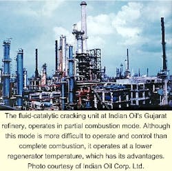
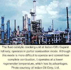
Indian Oil Co.'s Gujarat refinery has a partial combustion FCC regenerator operating in diesel-maximization mode. The unit is a side-by-side UOP unit with a capacity of 1.0 million tonnes/year.
In normal operations, its bottoms yield is 10-12 wt % and its CRC level is 0.3-0.4 wt % with a rare earth, ultra-stable Y-zeolite catalyst.
The performance of the unit deteriorated in October 1997. It experienced a high level of CRC and afterburn. In fact, the CRC level increased to 1 wt %. The higher CRC reduced the dynamic activity of the catalyst and thereby resulted in poor conversion and high clarified oil (CLO) yield (>20 wt %).
The high afterburn (60-70° C. vs. 30° C. during normal operations) caused a very high cyclone temperature. The unit also experienced a higher amount of catalyst loss during this period (1.5-2.0 tonnes/day vs. 0.5-0.75 tonnes/day during normal operations).
During two unit shutdowns, Indian Oil inspected hardware that it suspected of causing the problem. Although the company suspected an air grid failure, there was no significant damage to the grid.
The high CRC problem persisted for about 1 year. Indian Oil analyzed the problem with respect to the several factors:
- Feed quality variation.
- Fresh and equilibrium catalyst quality effect, if any.
- Process condition changes in reactor, regenerator, and stripper.
- Possible hardware malfunction.
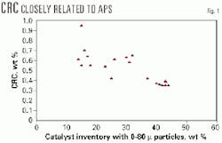
In its analysis,3 Indian Oil observed that the CRC maintained a close relationship with the circulating catalyst particle size (80
As the volume of 0-80
CRC also similarly increased when the APS of catalyst went above 100
The higher APS is mainly a result of higher catalyst loss. During one shutdown, the company observed that the cyclone had a number of holes in its body and connecting flanges. After repairing the cyclone, when the unit restarted, the catalyst loss significantly decreased and CRC level came down from 1 wt % to about 0.45 wt %.
After several months, however, the catalyst loss again picked up, and the CRC level increased.
The increase of CRC and corresponding reduction in the amount of fines in the circulating catalyst are mainly attributed to the shift in hydrodynamic regime in the regenerator from conventional dense bed to the bubbling bed. The regime shift was likely a result of:
The refinery observed that the air flow had decreased from 62,000 normal cu m/hr to 55,000 normal cu m/hr, and the APS had increased from 85
It is estimated that if the APS increases from 75
In another diesel-mode FCCU, despite high catalyst losses of 2.5-3.0 tonnes/day, the CRC level remained in the range of 0.3-0.4 wt %. Interestingly, the APS of the catalyst in this unit was quite good, in the range of 75-80
The superficial velocity in the regenerator was unusually higher (0.9-1.0 m/s). Higher velocity regenerator air resulted in expansion of the dense bed to the dilute phase and significant attrition of the catalyst in the air grid nozzle.
In such a situation, the higher catalyst loss was primarily a result of the expanded bed level and higher attrition of the catalyst, and therefore the APS did not increase. The CRC level remained in the normal range in spite of very high catalyst loss experienced by this unit.
Case study No. 2
Case 2 concerns an FCCU with partial combustion operation that experienced high CRC and afterburn associated with a new catalyst switchover. The data presented for this case study are collected from a side-by-side UOP FCCU at Indian Oil's Mathura refinery with 1.0 million tonnes/year of capacity.
It is easy to change the entire catalyst inventory of an FCCU in a period of 2-3 months because the unit uses a fluidized system. This ability gives operators a powerful way to attempt to improve the unit performance level.
In spite of elaborate tests on activity and product yields, when brought to the field, catalysts sometimes stabilize at much higher CRC levels than pilot tests or model predictions predicted. Some partial combustion FCCUs also experience higher afterburn than expected.
Table 1 summarizes regenerator-run data for four catalysts with respect to their performances and regenerator operating variables. Varying the zeolite-to-matrix (Z/M) ratio from 11.8 in Catalyst A to 1.74 in Catalyst D significantly improved the CRC level and degree of afterburn. The CRC decreased from 0.6 wt % to 0.3 wt %, and cyclone temperature decreased from 715 to 690° C.
It is interesting to note that the above improvements took place without much change in the regenerator temperature and air-flow rates. The actual reason behind the improvement in regeneration behavior is difficult to establish because there were also hardware changes in between the catalyst switchovers.
In fact, during the plant trial of Catalyst A, the regenerator operation sometimes was unstable with a high degree of afterburn. During these times, the regenerator temperature and CRC became very sensitive to the air flow.
These observations suggested that there must be certain catalyst parameters that affect the ease with which deposited coke on the catalyst burns. Based on further study, Indian Oil concluded that the coke-burning rate constant, defined as "regenerability," varies from catalyst to catalyst.
The company found that the Z/M ratio has a good relation with regenerability although there are many associated catalyst parameters, which play a direct or indirect role in regenerability. Detailed descriptions of the regenerability test and results are available elsewhere.3 4
Table 1 shows that the regenerator performances of the different catalyst are directly proportional to the regenerability constant, which gradually increased from 0.22 to 0.44 as Z/M decreased from 11.8 to 1.74.
Reduced afterburn DT with high matrix catalyst indicates efficient burning in the dense bed itself. This, in turn, implies better utilization of air in the bed; the air requirement decreased as Z/M decreased.
The effects of a lower Z/M ratio can be verified in other units running in partial combustion mode.
For instance, one such unit had a CRC level of 0.25-0.30 wt % and a low Z/M catalyst. When a new catalyst system with very high microactivity (above 78) and Z/M ratio was tried, the CRC level shot up to 0.75 wt % and the regenerator operation became unstable, causing three shutdowns of the plant.
In these situations, almost nothing wrong can be observed in the hardware in the post shutdown inspection because the root cause of the problem is the catalyst.
Thus, along with the usual activity and selectivity study, it is important to evaluate the regenerability of a new catalyst system for a partial combustion FCCU. Operating companies should also evaluate the performance of the catalyst based on expected CRC level with the new catalyst system.
Case study No. 3
Lower regenerator temperature can lead to high CRC and afterburn.
In partial combustion mode, operators usually control the regenerator temperature within 650 to 680° C. for efficient burning of the coke.
In some instances, however, particularly in operations with very low reaction temperatures or with very high feed rates and low activity catalyst, the regenerator temperature could run as low as 620° C.
In such situations, coke burning in the bed becomes very slow, and the air injected in the bottom breaks through to the dilute phase, which leads to significant afterburn.
It is important to note that although bed temperature remains very low, the cyclone temperature may run high as a result of excess oxygen present in the dilute phase.
The CRC also remains relatively high even if the feed being processed is light. In such cases, the coke yield is higher than expected as a result of CO formation, which is favored at lower regenerator temperatures.
Higher CO levels in the flue gas means less heat generation per unit of coke burned; therefore, coke yield is higher when regenerator temperature is lower. In fact, some of the old units that run at very low regenerator temperature (<600° C.) have coke yields above 6 wt %, as compared to 4.5 wt % coke yields in normal partial combustion FCCUs.
How can operators increase the regenerator temperature in these situations? Increasing air flow alone does not help because it further worsens afterburn.
Maximizing regenerator pressure, if there is any leeway to do so, may increase the regenerator temperature.
In addition, increasing the coke make on the reactor side by injecting a slurry recycle or increasing reactor temperature may help. If the catalyst and air distributor in the regenerator is not uniform, however, increasing coke make in the catalyst will lead to an even higher CRC level. In such situation, one of the proven solutions is to add a CO combustion promoter so that CO gets converted to CO2 in the dense phase.
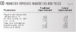
The regenerator temperature of the Gujarat refinery's FCCU was about 620° C. and the CRC was 0.5-0.6 wt % when Indian Oil decided to add a CO promoter to reduce the regenerator temperature. It added about 700 ppm of CP-3A, a CO promoter manufactured by W.R.Grace & Co., to the catalyst inventory.
Within 1 week after adding the CO promoter, there was a remarkable improvement in the regenerator performance. Table 2 summarizes the improvement in yield pattern, afterburn, and the regenerator temperature for which the promoter was responsible.
The regenerator temperature increased by about 18° C. while the CRC level and coke yield decreased. A low CRC level helps increase the dynamic activity of the catalyst, thereby increasing gasoline yield in spite of marginally higher feed rate.
Further details of the CO promoter application in partial combustion FCCU is described elsewhere.5
Case study No. 4
If radial temperature distribution is a concern, it is necessary to inspect the air and catalyst distribution in the regenerator.
A normal regenerator dense-bed temperature with a high cyclone temperature is a symptom of catalyst maldistribution in the regenerator or a faulty air grid plugging pattern, or both.
The Gujarat refinery faced such a problem in its FCCU. The temperature of one of its cyclones was 700° C., 15-20° C. higher than other cyclones. The air grid in this zone had 179 open holes.
Models indicated that a reduction in the cyclone temperature by 12-15° C. decreased the number of open holes to 129. This action brought the radial temperature difference among different cyclones to 3-5° C.6
Similarly, adoption of better internal hardware (for example, a ski jump) in the catalyst entry section from stripper standpipe to the regenerator could significantly reduce the CRC and afterburn level in partial combustion units.
References
- Mandal, S., Das, A.K., and Ghosh, S., "Effect of Coke on Catalyst in Distillate FCC Performance," Ind. Engg. Chem. Res. vol. 32, 1993, pp.1018-23.
- Letzsch, Warren S., Dharia, Dilip J., Chapin , Lark and Hunt, David," Stone & Webster FCC/DCC Technology and Its Application in India," Tenth Refinery Technology Meeting, Feb. 11-13, 1998, Mumbai, India, p. 33.
- Mandal, S., Das, A.K., Shah, S.K., Rao, M.R., Das, S.K., Badhe, R.M., Makhija, S. and Ghosh, S., "Coke Burning Problem in a Partial Combustion FCCU-Troubleshooting," Proceedings 3rd International Petrotech Conference & Exhibition, Petrotech-99, New Delhi, Vol. 2, 1999, pp. 165-72.
- Murthy, V.L.N., Debnath, S., Rao, M.R., Ray, S.K., Das, A.K., and Ghosh, S., "Development of a Test Method to Evaluate FCC Catalyst Regenerability," ACS Symposium series 634, Chicago, Chap. 29, 1995, pp. 401-12.
- Mandal, S., Bhattachrayya, D., Shende, V.B., Das, A.K., and Ghosh, S., "Impact of Additive Usage in Distillate Fluid Catalytic Cracking Operation," ACS Symposium series 571, Washington, Chap. 24, 1993, pp. 335-48.
- Rao, M.R., Singh, S., Das, A.K., Makhija S., and Ghosh, S., "Modeling of Air Distribution in FCC Regenerator," not yet published.
The authors
A.K. Das is a senior research manager at Indian Oil Corp. Ltd.'s research and development center. For the past 10 years, he has been engaged in different areas of FCC research, including modeling, process development, and catalyst evaluation.
Das holds a masters degree in chemical engineering from IIT Kanpur.
S. Mandal is a deputy manager of research at Indian Oil Corp. Ltd.'s research and development center. For the last 7 years, he has been engaged in FCC catalyst selection and refinery process development activities. He holds a masters degree in chemical engineering from IIT Kanpur.
D. Bhattacharyya is a deputy manager of research at Indian Oil Corp. Ltd.'s research and development center. For the past 9 years, he has been involved in FCC catalyst selection and refinery-process development activities. He holds a masters degree in chemical engineering from IIT Kanpur.
M.R. Rao has been working at Indian Oil Corp. Ltd.'s research and development center for the past 7 years. His areas of interest are resid FCC catalyst evaluation and FCC fluidization. He holds an M.Tech in chemical engineering from IIT Kanpur.
S. Makhija has more than 30 years' experience in process plant design and operations and research and development. His current research interests include refinery processes, pipeline transportation, pipeline corrosion monitoring, failure analysis, and residual life assessment.
Makhija holds a chemical engineering degree from IIT Delhi. He did post graduate work in chemical engineering at Ohio University, Athens, Ohio, and metallurgical engineering at the University of Missouri, Columbia.
S. Ghosh is general manager of Indian Oil Corp. Ltd.'s research and development center. His research interests include reaction engineering, scale-up design, and simulation of chemical processes. In the past 10 years, Ghosh has been engaged in research and development activities related to FCC. He holds a masters degree in chemical engineering from Calcutta University and a PhD in chemical engineering from Indian Institute of Science, Bangalore.


