Optimizing conditions, modifying design improve FCC regenerator
G. Saidulu
K.G. Palappan
M.K. Bhuyan
V.K. Satheesh
D. Bhattacharyya
S. Rajagopal
Indian Oil Corp. Ltd.
Haryana, India
A high-severity fluid catalytic cracking unit of 100,000 tonnes/year capacity has been in operation at the Guwahati refinery, one of the 10 refineries operated by Indian Oil Corp. Ltd., since its commissioning in 2003. While the design objectives could be achieved successfully, catalyst loss had been high. The best-achieved catalyst loss on a sustained basis was about 420 kg/day, which gradually increased to 650 kg/day.
A systematic step-by-step method was followed to identify the cause of the problem. Deficiencies in design of hardware internals and suboptimal process conditions were found to be the contributing factors.
Implementation of improved design of hardware internals along with optimization of operating conditions resulted in reduction of catalyst loss with efficient regeneration. This article presents the analysis and troubleshooting of the problem of very high catalyst loss, which led to improvement of regenerator performance.
Critical role
The FCC unit has become an essential part of a modern refinery. Worldwide, refiners are under pressure to process more residual feed stocks while maintaining conversion rates. Design and operation of the regenerator have become critical in achieving this objective.
Sometimes, we may achieve better regeneration of catalyst, but other problems such as higher catalyst loss or higher air requirement may limit either throughput or continuous catalyst regeneration (CCR) of the feed. Such problems can be overcome by improving the design of regenerator internals and optimizing operating conditions.
The most common parameters for monitoring unit performance are catalyst loss, equilibrium catalyst properties, air distribution, afterburn, catalyst inventory, and cyclone pressure drop.
The high severity FCC unit of 100,000 tpy capacity has been in operation at the Guwahati refinery since its commissioning. The unit, equipped with single-stage turbulent bed regenerator with complete combustion, was designed to process high CCR feedstocks such as atmospheric tower bottom. The spent catalyst is distributed over the top of the bed, while the air is distributed at the bottom. The temperature differential between the dense and dilute beds is controlled with no or minimum afterburn. The regenerator is equipped with one set of two-stage cyclones.
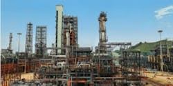
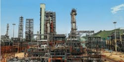
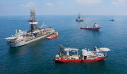
Indian Oil Corp.'s FCCU at the Guwahati refinery was the site of successful efforts to reduce catalyst loss (photo from Indian Oil Corp. Ltd.).
Higher catalyst loss
Higher catalyst loss from an FCC unit is always a concern due to the impact on operational stability, profitability, excessive erosion of equipment, environmental impact and sometimes product yield pattern. In well-designed and operated units, catalyst loss of less than 0.1 lb/bbl of fresh feed is achieved, which may increase typically to 0.15 lb/bbl of fresh feed in case of revamp due to compromise on certain design aspects to reduce the revamp cost. For example, in case of revamp, the regenerator may be operated at higher superficial velocity at more than 1 m/sec against 0.5-0.8 m/sec in the original design.
Excessive catalyst losses are common in FCC unit, primarily due to mechanical damage of reactor-regenerator internals, such as holes or cracks in cyclones or excessive erosion of air grid nozzles. Higher throughput than design, abrupt changes in operating conditions, and switchover to catalyst with poor physicochemical properties can also contribute to incremental catalyst loss, which gets aggravated in the presence of damaged internals.
In case of inadequate design with respect to velocity, cyclone placement, coupling arrangement as well as the basic design of cyclone, catalyst loss could be a perennial problem after commissioning. In such case, diagnosis becomes more difficult, since it is rarely possible to pinpoint the deficiency in design without verifying other underlying causes one by one.
In this unit, catalyst loss had been higher since commissioning. The best-achieved catalyst loss on a sustained basis was about 420 kg/day, which gradually increased to 650 kg/day against the design value of 160 kg/day. The design catalyst was more than the typical value primarily due to higher wall effects owing to very low capacity. A systematic step-by-step method was followed to identify the root cause of the problem.
Regenerator air distributor
Catalyst and air distribution are important factors for improving regenerator efficiency. Among various grid forms, manifold grid allows solids to flow from above the grid to below. The manifold grid also provides good turndown ratio and undergoes thermal expansion without damage, and holes can easily be shrouded.
Gas jetting from the orifice picks up the surrounding particles, which subsequently get accelerated and collide with each other as well as with other particles at the jet surface. As shown in Fig. 1, in upwardly directed jets, the particles are picked up at the orifice edge and travel a longer distance into the bed, while in downward directed jets, the particles travel a shorter distance and impinge on bed and internal surface of the regenerator shell. The downward directed jets have higher attrition rates than upwardly directed jets.
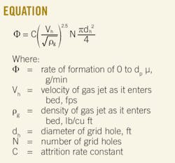
The rate of attrition can be estimated by the equation shown in the box below.1
Table 1 gives the attrition rate constant for downwardly directed jets impinging FCC catalyst particles.1 Rate of attrition is proportional to jet velocity.
In the unit under study, a downward manifold air distributor is provided for uniform distribution of regeneration air.
Cyclone system
A properly designed and maintained cyclone system is crucial for minimizing catalyst loss. The vapor-gas along with entrained catalyst enters the primary cyclone and moves downward in a spiral due to centrifugal and gravitational forces.
Separation of gas and particle takes place as a result of the difference in centrifugal forces owing to difference in their masses. The gas going with the catalyst takes the return path in the dust hopper or vortex breaker. The solids return to the fluidized bed through dust hopper and dipleg.
Two-stage cyclone systems are employed for separating the catalyst from the hydrocarbon vapors in the reactor and flue gas from the regenerator. According to the cyclone vendor's data sheets, the cyclones were designed for 80 kg/day in both reactor and regenerator.
Troubleshooting
The higher catalyst losses could be either from regenerator or reactor or sometimes from both.
The first step is to assess whether the major losses are from the regenerator or reactor side. Once this is determined, cyclone performance is to be examined from the standpoint of operational and mechanical integrity and cyclone design.
A systematic step-by-step method, as shown in the following, identified the cause of the problem of higher catalyst loss.
1. Assess whether the increased losses are from the regenerator or reactor side. Catalyst fines particles were collected from the main fractionator by burning off the slurry oil and tested for the weight, particle size distribution (PSD), and average particle size (APS).
The data in Table 2 show that catalyst loss through the reactor was less than 20% of total catalyst loss. APS of the catalyst fines was found to be less than 5 μ, which further supported that the major catalyst loss was through regenerator side.
2. Monitoring of physical properties of fresh catalyst and equilibrium catalyst. The change in physical properties of fresh catalyst such as higher attrition index, higher fines content (0-20-μm particles), and lower average bulk density (ABD) can lead to higher catalyst loss. With equilibrium catalyst (E-cat) data, the same can be monitored for any change.
Under constant properties of fresh catalyst, an increase in APS of E-cat indicates the higher catalyst loss due to decreased collection efficiency of cyclone separators, and reduction in APS indicates increased attrition.
The change in properties of fresh catalyst was within the industrial standards and incremental catalyst loss was not expected to be contributed by fresh catalyst. Table 3 summarizes the physical properties of E-cat. An E-cat report showed more fines content even with high catalyst loss. This could be due to the higher attrition in the regenerator.
Attrition occurs mainly from a breakdown of the coarser particles of more than 40 μ size. In an FCC unit, attrition is principally the result of jet impingement. The attrition resulting from the mixing and churning is usually negligible.
Therefore, the major sources of attrition are air grids and cyclone separators owing to higher velocities. Further, downward-directed air grids generate more fines than upwardly directed jets. Higher gas jet velocities could also increase entrainment rate. Catalyst retention in the unit is likely to reduce at higher jet velocities.
3. Air distributor modification. In this unit, the regenerator air grid is a cross bar manifold type with uniform diameter nozzles. Air jets are downwardly directed with jet velocity of more than 55 m/sec. Higher jet velocities generate more fines and require more air for regeneration of the catalyst for a given coke yield.
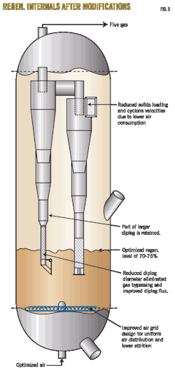
Considering the higher attrition at the nozzles, we changed the design of the air grid. The air grid holes were modified from single to dual diameter to reduce nozzle tip velocity to 18.5 m/sec while maintaining the central pipe, manifold pipe, and number of holes. This resulted in a reduction of jet penetration length to 150 mm from 210 mm as well as reduction in air requirement by about 20%.
The modified air grid provided the cushion to reduce the regenerator bed's level while ensuring full combustion. Due to reduction in superficial velocity, stable CO burning could be achieved even at lower bed height without adding CO combustion promoter due to improved regeneration.2 Solids loading to the cyclone also reduced due to the reduction in superficial gas velocity.
After modification of air grid, 0-40 μ fraction in E-Cat came down gradually to 2 wt % from 5 wt % and APS increased to >100 μ from 85 μ. Fig. 2 shows a hift in APS and fines content (0-40 μ and 0-60 μ) of E-cat before and after air grid replacement. It can be seen that catalyst attrition slowed significantly after modification of air grid. Interestingly, even though the catalyst attrition was slowed, the catalyst loss was higher.
4. Particle-size distribution of fines content in flue-gas stack. Fig. 3 shows the change in PSD of fines content collected from the bottom of the flue-gas stack before and after replacement of the air grid. After modification of air grid, APS of the fines collected at the bottom of the flue-gas stack increased to 44 μ from 31 μ. The result confirmed a significant reduction in attrition after modification of air grid.
Fines collected at the bottom of the flue-gas stack after air grid modification showed the presence of 60-80 μ particles. Fig. 3 also shows a decrease in the magnitude and shift to coarser particles. This shows that even coarse particles were escaping from the second-stage cyclone.
5. Mechanical damage of cyclones. Leaks due to weld cracks, holes in the cyclone body or the dipleg, blockage or plugging of the dipleg, or a stuck or inoperative dipleg valve can also increase catalyst loss. In the case of mechanical damage of the cyclone, higher temperatures and lower pressure drop across the cyclones can be observed.
Historical data showed a negligible change in cyclone temperatures and pressure drop in the unit. During shutdown, mechanical integrity of the cyclone system was confirmed. Since particles collected from the bottom of the flue-gas stack were smaller than 80 µ, it can be concluded that there were no holes in the cyclones.
Solids rate and PSD at the inlet and outlet of the primary and secondary cyclones were estimated. PSD of fines samples of flue-gas stack bottom closely matched with that of the particles leaving the primary cyclone. Therefore, it could be presumed that secondary cyclone performance was poor.
6. Trickle valve operation. The secondary cyclone dipleg is equipped with a trickle valve immersed in the catalyst bed. In the trickle valve, the differential pressure across the valve tends to push the flapper closed. To balance this force on the valve, catalyst level builds up in the dipleg, creating a hydrostatic force to open the flapper. The weight of the flapper creates an additional force that must also be overcome by the catalyst level.
Sometimes, these valves become stuck or inoperative due to higher bed level or sudden pressure fluctuations. Normally, such problems can be overcome by reducing or increasing the regenerator levels. Similar exercises were carried out to ensure that the trickle valve comes to a normal position and no reduction in catalyst loss could be observed. In the presence of lower fines content and higher residence time of the particles, dipleg operation worsens due to deaeration of the bed inside the dipleg.
7. Inlet velocity and location of the cyclones. A properly designed two-stage cyclone system can attain overall catalyst fines recovery of greater than 99.99%, when cyclone velocities and dipleg mass flux are within acceptable ranges. Theoretically, the efficiency of cyclones increases with increasing inlet velocities (Fig. 4).
In practice, however, the efficiency of the cyclones deteriorates after certain velocity,3 leading to incremental erosion of internal refractory at the inlet, exit, barrel, and hopper cone and leading to discontinuation of the path of the descending gas stream, i.e., descending spiral diverts towards the exit gas stream before separation of particles.
This would further aggravate in smaller cyclones (similar to the current case) as regular maintenance of the refractory is difficult. During shutdown, it was observed that the refractory of the barrel and the dust hopper portion was severely damaged. This could be one of the reasons for reduced performance of the cyclone over a period. Designers follow a standard range of inlet velocities to overcome these effects. The primary and secondary cyclones' inlet velocities were considerably reduced after modification of air grid (Table 4).
Cyclones are located above the transport disengaging height (TDH), which is essentially the height above the regenerator dense bed at which the particle entrainment or dilute phase density shows only a negligible change with further increase in height. Due to change in operating conditions such as regenerator level, higher air rate, or lower pressure, TDH increases and cyclone location may fall within TDH, which increases the solids loading to cyclones and higher catalyst losses. In the present case, the calculated TDH was found to be in order.
8. Operating conditions. Higher regenerator air flow leads to higher superficial velocity, catalyst loading to the cyclones, as well as catalyst loss. The historical data of the unit showed that it was operated at varying throughput ranging from 100-130% of design with marginal change in catalyst loss.
The regenerator dense bed level also plays an important role in the performance and stability of the cyclone systems. High or low regenerator bed level can result in significantly increased catalyst losses. High level will result in flooding of the dipleg and reentrainment of catalyst to the cyclone outlet. Low level can affect the cyclone pressure balance and cause bypassing of gas and catalyst up the dipleg from the bed. The probability of this occurring is greater in the second-stage dipleg because mass flux is lower.
Level indications were confirmed by a pressure survey. Controlled data were also generated by conducting test runs at different throughputs and regenerator levels; no significant reduction in catalyst loss could be observed.
9. Dipleg operation and design. The pressure inside the cyclone above the dipleg pipe is lower than the pressure in the freeboard of the regenerator. Due to lower pressure and density inside the dipleg, the catalyst level within the dipleg is above the regenerator bed's level by a height equivalent to the cyclone system's pressure differential. The maximum catalyst level in a dipleg should be 2 ft minimum below the hopper-dipleg's weld line.
Pressure balance across the regenerator's cyclone system was worked out based on single-gauge pressure survey data and the same along with densities used (Table 5). It was seen that primary cyclone dipleg had more than 6 ft free space after satisfying the pressure balance, whereas in secondary cyclones, the required catalyst level was more than the dipleg length (dipleg flooding).
When this occurs, part of the catalyst will be reentrained and lost along with exiting gas causing additional catalyst loss. In addition, this leads to attrition of catalyst and erosion of cyclone cones and hoppers.
Subsequently, the unit was operated at lower regenerator bed level to ensure at least a 2 ft gap between the surface of catalyst level in the dipleg and dust hopper cone-dipleg's weld joint. The results showed marginal reduction in catalyst loss, to 550 kg/day from 650 kg/day.
The catalyst flow in the first stage dipleg will be 99-99.5% of inlet loading. Therefore, the loading to the second stage dipleg will be 0.5-1% of the loading of the first-stage cyclone. The estimated dipleg catalyst mass flux of secondary cyclone was found to be less than 1 kg/sq m sec. In the absence of sufficient catalyst flux (due to outsized dipleg diameter), gas bypassing from the bed into cyclone through dipleg may occur. Intermittent puffing of catalyst was also observed in the flue-gas stack. Lower flux could be one of the reasons for puffing of catalyst through flue-gas stack.
From this analysis, it was concluded that the secondary cyclone dipleg length and diameter were more than required. Accordingly, it was decided to reduce the same to improve the catalyst flux and maintain the proper catalyst level in dipleg.
10. Cyclone hardware modifications and optimizing operating variables. Based on this analysis, the dipleg length and diameter of the regenerator's secondary cyclone were reduced to ensure adequate catalyst flux as well as more than 2 ft differential height between catalyst level in the dipleg and dust hopper cone-dipleg weld joint. The damaged refractory was repaired. The reduction of dipleg's length also allowed the operation at lower regenerator bed level, which in turn resulted in faster replacement of catalyst leading enhancement of catalyst activity.4
After implementation of these modifications, catalyst loss came down to 250 kg/day from 650 kg/day. Analysis of the E-cat showed improvement in 0-40 μ fines content to 8 wt % with reduction in APS to 89 μ. Table 3 illustrates the shift in APS and fines content of the E-cat before and after air grid replacement and cyclone modification.
Microactivity-test activity of the E-cat also increased by more than 5% even with a lower fresh catalyst addition rate of 350 kg/day due to increased retention of fresh catalyst particles resulting from reduced attrition and catalyst loss and to faster replacement of catalyst, as previouisly stated. Fig. 5 shows the schematic of regenerator internals after modifications.
In the revamp of existing FCC units—either in terms of capacity, incremental processing of residue feedstock, or improving conversion to produce more light olefins—the coke-burning capacity of the regenerator can become a bottleneck. Adopting an approach such as the one set out in this article can improve regenerator performance within the operating window.
References
1. Zenz, F.A., "Studies of Attrition in Fluid-Particle Systems," NSF workshop, Rensselaer Poly. Inst., Troy, NY, Oct. 17-19, 1979.
2. Santner, C.R., and Letzsch, W., "FCC regenerator design: Part II," PTQ, second-quarter 2008, pp. 37-43.
3. Kalota, S.A., and Rahmim, I.I., "Solve the five most common FCC problems," AIChE Spring National Meeting, New Orleans, Mar. 30-Apr. 3, 2003.
4. Letzsch, W., and Santner, C.R., "FCC regenerator design: Part 1," PTQ, first-quarter 2008, pp. 63-67.
The authors
Gadari Saidulu ([email protected]) is a process engineer in Indian Oil Corp. Ltd., research and development center. Before joining Indian Oil, he worked in the Department of Atomic Energy for the government of India as a production engineer. He holds a masters in chemical engineering from the Indian Institute of Technology, Madras. He is a fellow of Indian Institute of Chemical Engineers.
Ganesh Palappan Kanakaraj ([email protected]) is a research officer at the research and development center of Indian Oil. He holds BE and ME degrees in chemical engineering from Annamalai University and a PhD in fluidization engineering from the Indian Institute of Technology, Madras.
Manoj Kumar Bhuyan ([email protected]) is a process engineer for Indian Oil's research and development center. He holds a masters in chemical engineering from the Indian Institute of Technology, Kharagpur.
Vetterkunnel Kumaran Satheesh ([email protected]) is research manager at the research and development center for Indian Oil. He holds a masters of technology in chemical engineering from the Indian Institute of Technology, Kanpur.
Debasis Bhattacharyya ([email protected]) is a senior research manger in the research and development center for Indian Oil. He holds a B.Tech in chemical engineering from Calcutta University and M.Tech from the Indian Institute of Technology, Kanpur. He is a member of Indian Institute of Chemical Engineers.
Santhanam Rajagopal ([email protected]) is a postgraduate in chemical engineering from IIT, Chennai. He has held various positions in refineries and in technical and project departments in refinery headquarters at Indian Oil.
More Oil & Gas Journal Current Issue Articles
More Oil & Gas Journal Archives Issue Articles
View Oil and Gas Articles on PennEnergy.com
