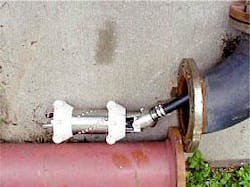
Field experience shows how to inspect odd, noninspectable platform risers
Recent field experience has proven the use of new inspection tools on odd (that is, geometrically eccentric) risers.
Described here are three successful inspections of odd, small-diameter riser configurations for three different operating companies in Alaska, Chile, and California. These experiences have resulted in an increasing range of equipment for the inspection of such risers from a single access point at the platform.
The problem
Platform risers must be in condition not only to ensure smooth and safe operations but also to protect the environment. Checking their condition requires inspection.
Although almost all long-distance pipelines, even old lines, are piggable today, many risers cannot be inspected by product-propelled pigs. Particularly on older platforms, risers were not designed to allow inspection by pigs because they sometimes contain tight bends, forged T-connections, and other ID restrictions that prohibit the passage of pigs.
In some cases, risers even terminate at a T-connection, which prevents the use of a product-propelled tool altogether.
Some risers may be inspected from the outside, which requires thorough external cleaning. Nevertheless some parts, at clamp locations for example, remain uninspected due to inaccessibility.
As a result, until recently, a considerable number of odd platform risers escaped inspection through lack of effective and affordable solutions. Renewing the license to operate the platforms, however, requires that the conditions of these "non-inspectable" risers be established. Hence, a special tool has been much in demand.
Survey, solution
Following a market survey, Unocal Corp. Oil & Gas Operations, Anchorage, selected the Dutch inspection company Röntgen Technische Dienst to design a tailored riser-pipe inspection tool and provide the inspection services.
The main reason for selection was the company's experience with cable-operated ultrasonic tools for internal inspection of offloading lines and its in-house engineering capacities to adapt such tools for a specific riser geometry. Such cable tools are operated from one open end.1-4
Common fluid-propelled pigs usually are not reversible and, therefore, cannot be used to inspect loading and offloading lines because they terminate at an impassable subsea manifold. Moreover, odd geometric pipeline features, such as mitre bends, abrupt diameter changes, and so forth, prohibit deployment of a common pig.
For inspection of these pipelines, ultrasonic tools suitable for a diameter range of 6-60 in. with low friction cable of up to 17,000 m have been developed.
In addition to safety, use of the cable allows full control over the movements and performance of the tool and provides real time results for immediate interpretation.
Reengineering of the existing cable tools created a solution that complied with the basic requirements of Unocal, the launching customer.
Ultrasonic standoff technique
Experts in nondestructive testing agree that the ultrasonic (UT) standoff technique is the most suitable method for quantifying and differentiating between internal and external corrosion.
Unlike magnetic flux leakage technique, UT functions independently of tool speed and provides absolute and accurate data. But, UT also requires the pipe wall to be relatively clean.
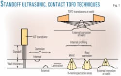
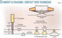
UT probes are mounted in a circular array at some distance from the pipe wall, allowing simultaneous measurement of both internal corrosion and pipe wall thickness. Fig. 1 shows the type of defects that are detectable with standoff UT.
Although the standoff method allows inspection very close to the circumferential weld (no lateral dead-zone), the weld volume cannot be inspected.
For standoff UT inspection, the pipe must be filled with a liquid that serves as an acoustic couplant. Either the crude oil or liquid product already in the pipe or seawater may be used.
A very attractive feature of the relatively large standoff distance (up to 150 mm) is that it allows the tool to pass severe local diameter reductions and other obstacles. Moreover, it provides information on the internal profile of the pipe such as the presence of often-unknown ovalities, dents, or buckles.
Identical to the tools for inspection of loading and offloading lines, the riser inspection tool can be deployed from a single point somewhere on the platform. The most convenient location always is agreed upon with the operator during a prior site visit; this is essential for a tailored solution.
To allow the passage of bends, the tool consists of several articulated slim bodies that are connected by a cable to the electronic equipment on the platform. The first generation of tools was lowered by gravity; thus only the first vertical part of the riser could be inspected. The following generations of tools are equipped with a motor drive unit to enter horizontal parts of a riser and inspect parts of the pipe on the seabed.
The following sections describe three inspection cases that illustrate that each job is different and requires a tailor-made solution. The ongoing tailoring and improvements, in turn, create a gradually growing number of possibilities that can be used or provide inspiration for other "noninspectable" risers.
Case 1: Cook Inlet
Unocal operates 10 subarctic platforms in the upper Cook Inlet, built in the late 1960s, that produce oil and gas. On each platform, up to 10 risers are installed, all externally exposed to corrosive seawater.
The platforms are in an environmentally sensitive area so that, where possible, potential corrosion of some risers was carefully monitored by regular visual inspection.
Only in recent years has some external corrosion of the risers in the splash and tidal zones been reported. This observation created the impetus for a sophisticated riser inspection program.
There are different riser configurations: J-tubes on the inside of a platform leg and on the outside and inside a pull tube. The 6-12 in. OD risers are made of heavy-wall pipe with a nominal 12.7 mm WT. It was Unocal's intention to inspect the risers themselves down to the lower bend, totaling to some 60 m.
Use of intelligent long-distance pigs was rejected for the following reasons:
- Zone of interest was only 60 m.
- There were excessive time and costs involved with long-distance intelligent pigs.
- Most riser configurations contained a multiple of tight bends prohibiting passage of pigs.
- There were no appropriate pig traps.
Unocal studied alternative options for inspecting these risers. Because some of them are encased, they are inaccessible from the outside. Unocal concluded that internal ultrasonic inspection of the riser with a tool using a cable was the only feasible and affordable solution.
Selection of vendor; inspection tool
For the vendors invited to tender for the required inspection services, Unocal's requirements were the following:
- Capability to inspect heavy-wall pipe.
- Differentiation between internal and external corrosion.
- Operation capability in both oil and water.
- A positive retrieval mechanism.
- One-end launch and retrieval.
- Inspection tool and equipment compactness and helicopter transportability.
- Minimum manpower.
Unocal selected RTD from 16 other inspection vendors to perform the inspection with a tailored riser-pipe inspection tool.
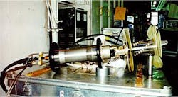
With the platform operator's requirements in mind, RTD built a first-generation riser tool with cable. As the tool was to inspect the vertical part of the riser only, it was decided to employ gravity to lower the tool. Fig. 2 shows the tool, consisting of two articulated bodies, ready for deployment.
The right side of the picture shows the sensor body with a large number of probes. This figure also shows flexible disks that center the sensor body in different pipe diameters. Proper centering is essential for good UT performance.
At left, the frontend electronic body is shown connected by cable to the compact set of electronics nearby on the platform to operate the tool. This set of electronics also allows on-line presentation and instant interpretation of results. The acquired data on internal profile and wall thickness are presented in a coherent color-enhanced map. Naturally, all data collected are stored for later retrieval.
The tool is lowered and lifted by a separate chain and a motorized hoisting device.
Contrary to self-contained intelligent pigs, cable tools provide the data before demobilization. If necessary, an additional inspection run can be made. This is an important advantage of cable-operated tools.
Corrosion of a riser can occur randomly. Therefore, full circumferential surface coverage is required. Several staggered probes, equally distributed around the circumference of the sensor body, provide this high coverage.
Before shipment of the equipment, in-house experiments in a test loop showed proper performance of the tool. The total weight of this first generation system was less than 500 kg. A two-man crew can operate the tool.
Concept; site preparation
The riser inspection tool can be used to inspect both crude and gas risers.
A crude riser only requires depressurizing and opening. Inspection can be performed in crude during a very short downtime.
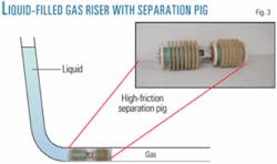
The gas riser must be filled with seawater. To prevent the entire gas line having to be filled with seawater, a specially developed procedure uses high-friction separation pigs with good sealing properties (Fig. 3). These are pumped down the riser by a metered amount of water.
Although crude oil is usually suitable as acoustic couplant, seawater in combination with separation pigs is preferred to replace the hydrocarbon for reasons of safety and cleanliness.
An additional advantage of the separation pigs is their capability of removing excess wax, if present. This is very beneficial to ultrasonic inspection: The cleaner the pipe wall the better the performance of the ultrasonic system.
Altogether there are several dozens of oil and gas risers on the 10 platforms. To keep the shutdown time and inspection costs to a minimum, it was decided to inspect a limited number each year.
Riser inspection was, therefore, prioritized based on the following criteria:
- Risers with recently reported corrosion.
- Desired information from key gas risers.
- Determination of condition difference between pull tube and J-tube risers.
- Low inspection priority on recently installed risers.
The first inspection in 1996 consisted of seven risers with the intention to inspect more annually. The number of risers presented for inspection in the following years would depend on the results of previous inspections and budget available.
First inspection, results
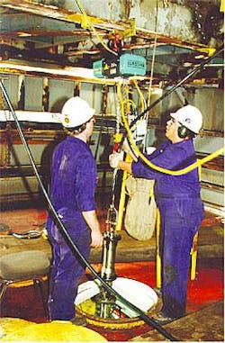
Fig. 4 shows the inspection tool on a platform being lowered just above the riser.
In general, as anticipated, one inspection run was sufficient to establish the condition of a riser. A single inspection run took up to 1 hr. Measurements were done during lowering and lifting of the tool. The tool performed to expectation.
As expected, after approximately 30 years of service, a few of the seven inspected risers showed some external corrosion. In one riser, indications with strong evidence of serious external corrosion very near to and possibly in the weld, could not be quantified. The dead zone of the system applied made it is impossible to detect or quantify corrosion in the weld itself (Fig. 1).
It was agreed that the inspection company should investigate the possibility of further analysis of this suspect location during a future inspection. There was no indication of internal corrosion in any of the risers.
Unocal was satisfied with the valuable and cost-effective inspection. This fact and the need further to analyze the suspect riser weld area made Unocal decide to order a new inspection program for 1997.
For analysis of the suspect weld area it was decided to apply "time of flight diffraction" (TOFD), a proven ultrasonic method in the nondestructive testing industry primarily developed to size defects mostly in welds. A TOFD module was developed that could be attached to the frontend of the existing riser-pipe inspection tool.
The TOFD method uses a pair of contact angle beam probes operating in "pitch and catch" mode, covering the weld volume (Fig. 1). This eliminates the dead zone of straight beam probes.
Analysis; further inspections
Based on the satisfactory in-house performance of the TOFD module, Unocal ordered reinspection of the suspect riser and inspection of a number of risers not inspected so far. The TOFD inspection on the suspect riser was performed after completion of the corrosion scan.
The pair of TOFD-probes was rotated over the full circumference while the data were collected, stored, and simultaneously processed, with on-site interpretation.
A part of the riser weld was indeed seriously corroded. The remaining wall thickness could be measured. The depth of the corrosion in the weld turned out to be similar to the corrosion in the adjacent pipes.
The remaining risers were inspected for possible external corrosion. Additionally some welds were inspected with the TOFD module. As before, the inspection proceeded quickly and smoothly. No more severe corrosion was found.
By yearend 2003, six annual inspection programs had been carried out on several dozens of risers and more are planned. Some of these are repeat inspections to verify and monitor corrosion rate.
Case 2: Straits of Magellan
Empresa Nacional del Petróleo (ENAP), Punta Arena, Chile, operates dozens of platforms in the Straits of Magellan. These platforms were built in the 1970s, and their risers were in need of inspection for, in particular, external corrosion. Of more than 200 oil and gas risers, ENAP decided to inspect about a quarter of them.
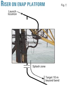
Diameters ranged 6-10 in. with a nominal 12.7 mm WT. Some of these risers, however, contain up to four 90° bends, totaling 360°. Fig. 5 shows this configuration.
The bends have radii of 15 D. Unfortunately, each riser contains one forged unbarred T-connection at some distance from the pig-trap. Additionally, this T-connection has an ID reduction of some 10%.
Another requirement of ENAP was to inspect a 10-m section of the horizontal pipeline on the seabed, totaling about 100 m.
Based on similar considerations as Unocal, ENAP also opted for the use of a cable-operated riser inspection tool.
The described riser geometry required construction of a second-generation tool. Its main characteristics are:
- Flexible enough to pass all bends and T-joints.
- Motor driven, to move the tool through the horizontal topside piping after the passage of some of the bends and ultimately to drive the10 m into the pipeline on the seabed.
A second-generation tool was built with a total length of 2 m consisting of several articulated bodies, including a motor-drive unit, to allow passage of bends with radii ≥ 5D.
The sensor head consists of straight-beam probes only to detect possible random internal and external corrosion and to measure wall thickness. For passing through the unbarred T-connection behind the launch location, a long shoehorn device was prepared to guide the tool across this obstacle.
A longer cable was made to accommodate the longer distances to be covered. The total weight of the second-generation tool was nevertheless still acceptable for transport by helicopter.
Inspection
The selected oil-and gas risers were inspected with the motor-driven system.
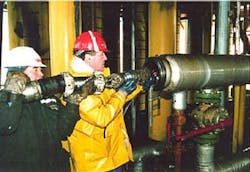
Fig. 6 shows the tool being inserted in a horizontal launch trap. The inspection commenced in 2002 and was completed in 2003 in three scheduled mobilizations.
During the first interruption, some of the tool-bodies were modified to ease the tool through the forged T-connection. During the last interruption, the motor drive unit was made more powerful to increase the horizontal range of the tool.
For inspection of the risers, a new type of separation pig with a special disk arrangement, increased certainty of sealing. This is particularly important on gas risers. Positioning of these pigs usually takes a few hours. Seawater was used to fill the risers.
Once the equipment was installed on the platform, usually two risers could be inspected in a 12-hr day. Inspection in both directions of a riser of more than about 100 m took 3 hr net.
Altogether, about 50 risers, mainly gas, were inspected. Some local external corrosion of the riser was detected, most of it above sea level. Reinspection of one of the risers showed the extremely good reproducibility of the results.
Case 3: Offshore California
Nuevo Energy Co., Bakersfield, Calif., operates a few platforms with subsea- connection riser configurations.
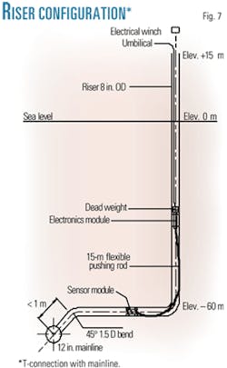
Risers are usually connected to a pipeline with about the same nominal diameter. These risers, however, are interconnected to the subsea main pipeline by T-connections. The subject 8-in. risers also contain a tight bend (1.5 D) on the sea floor.
As the riser is inaccessible from the outside, it could only be inspected from the inside with a reversible cable-operated tool. The challenge was to inspect the entire 8-in. riser and connecting horizontal section on the sea floor up to the unbarred 90° T-connection at 15 m beyond the 1.5 D bend, totaling some 60 m. Fig. 7 shows this riser configuration.
A suitable cable-operated inspection tool did not exist at that time. Hence, a special tool had to be engineered.
First an oil riser was to be inspected. Once the inspection had been executed and the good performance of the special tool proven, a gas riser of the same configuration was to be inspected for corrosion.
Third-generation tool
The solution was to use parts of the existing hardware of the small-diameter riser inspection tools built in recent years, as described in Cases 1 and 2. In fact, the sensor module was now connected to its electronics by an extremely long, sturdy but slightly flexible cable rod instead of being part of the articulated assembly.
The assembly was to be lowered by gravity. The sensor module had to be pushed to the far end of the line on the sea floor up to the T-connection. To detect corrosion, the sensor module contains straight-beam probes only.
Fig. 8 shows the sensor module attached to the cable rod during a rigorous in-house proficiency test in a full-scale mock-up.
The oil riser was inspected successfully in early 2000. The condition of the riser could be established from the gathered data. The system worked well.
As a result, the gas riser was inspected in autumn 2002. Both the oil and gas risers and the whole pipeline were filled with water as acoustic couplant. Both jobs lasted 3 days each including mob and demobilization by boat.
Recent developments
Development of a strong, compact crawler has been completed and field proven, as has been a cable with a low friction value to inspect longer parts of the connecting pipe on the sea floor.
Work has been finished on a rotating sensor head that guarantees full circumferential coverage in one inspection run for riser diameters ≥ 6 in.
New separation pigs are better able to pass varying internal diameters and still maintain position and sufficiently clean the pipe wall.
And, use of fiberglass optics, for long-distance data transmission as already used on a fluid-propelled tool,3 is being considered for inspection of long lengths of odd riser and pipe configurations.1
Acknowledgments
The authors thank Unocal, ENAP, and Nuevo Energy for permission to discuss the three cases of successful odd-riser inspection.
References
- De Raad, J.A., "Cable and other ultrasonic pigs," Pipes and Pipelines International, March 1990, Vol. 35, No. 2.
- De Raad, J.A., "Experience with cable-operated ultrasonic pigs for pipeline and riser inspection," NACE Annual Conference and Corrosion Show, Corrosion95, Orlando, 1995.
- Van Agthoven, R., "Ultrasonic inspection of risers: a new and simple approach," NACE Annual Conference and Corrosion Show, Corrosion98, San Diego, 1998.
- De Raad, J.A., "Ultrasonic inspection of risers: a simple and affordable alternative to self-contained pigging," Insight, Non-Destructive Testing and Condition Monitoring, June 2001 (Vol. 43, No. 6), pp. 399-403.
The authors
Robert van Agthoven has spent the last 12 years as sales manager for Röntgen Technische Dienst (RTD), the Netherlands, and spent 17 years in the company's research and development group, managing the development and field introduction of several remote operated inspection systems. As sales manager, he responsible for marketing services to inspect pipelines and risers with cable operated tools. Van Agthoven graduated in 1969 as a mechanical engineer from the Technical High School in Rotterdam and has been with RTD for more than 33 years.
Jan A. de Raad recently retired as manager of research and development at Röntgen Technische Dienst where he had worked for 40 years. He joined the company after 2 years with the Royal Dutch Air Force following his graduation in 1957 as a flight engineer from the Technical Aviation College in The Hague.
