Subsea gas compression hydrate formation analyzed
A study focused on potential hydrate formation in the pipe that connects the separator to the planned Ormen Lange subsea compressor.
Subsea gas compression is a new technology, and this article summarizes the results of an analysis of the potential for hydrate formation in the subsea compression station when it operates at steady conditions.
To maintain production levels in the future, Ormen Lange will require offshore gas compression, and the field’s operator has selected subsea gas compression as an alternative to the base-case of having compression on a floating platform.
StatoilHydro and its partners are now designing and building a full-scale pilot unit that will operate for a minimum 2 years in a seawater filled basin at the Ormen Lange onshore plant at Nyhamna.
In subsea gas compression, gas-liquid separation takes place upstream of the compressor unit, and thus this study will assess the hydrate inhibition strategy with respect to the Ormen Lange subsea compressor station.
Ormen Lange
Ormen Lange gas field is about 100 km off Norway in 250-1,100 m of water. StatoilHydro ASA, AS Norske Shell, Petoro AS, BP Norge AS and Esso Exploration and Production Norway AS are partners in the development.
The field started producing in September 2007 from subsea facilities tied back to an onshore processing facility at Nyhamna, on Norway’s west coast. It is the second largest gas discovery off Norway, with estimated initial recoverable gas reserves of 375 billion cu m (dry sales gas volumes).1 2
Production from the field will satisfy eventually about 20% of the UK’s gas consumption.
Ormen Lange is in a prehistoric slide area with an uneven sea bottom that has local 60-80 m high summits. The slide’s back wall is steep, up to 26°. Environmental conditions are also severe.
Hydrate formation
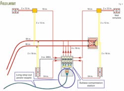
Subsea compression in recent years has been the subject of several studies.3-5 Reference 5 provides a detailed description of the subsea compression planned at Ormen Lange (Fig. 1).
Gas hydrates are crystalline ice-like structures wherein gas molecules are trapped in cages formed from hydrogen-bonded water molecules.6
Hydrate crystal morphology differs for various hydrocarbon mixtures. This means that in some cases the hydrocarbon liquid phase transports the crystals as dispersed particles, while in other cases the hydrate crystals form deposits on the pipe walls.
Hydrate formation is a major threat for forming blockages in long flowlines transporting unprocessed gas along the seabed.7 8 The threat can be controlled by adding hydrate inhibiting chemicals but the ultimate solution is to maintain flow without using chemicals or at least with using a minimum amount.
Extensive research on underinhibited systems or systems operating within the hydrate region without inhibitors is ongoing currently.9
No compression system in the world is designed to compress water-wet hydrocarbon gas at a temperature below the hydrate formation temperature. The Ormen Lange subsea compression system has to do this; so that the process design and hydrate formation properties for the field are different than for any existing compression operation.
This study aimed to secure efficient and effective long-term full scale (single train) pilot testing in Nyhamna to avoid for example long delays in testing due to hydrate problems.
The Ormen Lange subsea compression project identified that hydrate formation inside the compression station might lead to operational problems. Upstream of the compression station there is no problem because the Ormen Lange flow assurance strategy creates conditions in which the flow is always sufficiently inhibited against hydrates.
Monoethylene glycol (MEG) is added to the well stream (gas at dewpoint) at the templates to prevent the condensed water from forming gas hydrates. The design concentration is 60 wt % at the pipe outlet, which means that the concentration of the lean MEG at the wellhead is significantly higher (90 wt %) to make up for the dilution by the condensed water along the flowline. Formation water breakthrough is not expected, but should it appear, the well needs to be shut in. If the MEG injection is reduced, stopped, or insufficient with respect to concentration, the well also needs to be shut in.2
The hydrate strategy needs to be verified for a subsea compressor station placed near the wellhead. This means that normal operation (no formation water) with respect to hydrate formation and remediation should be verified. All calculations and conclusions discussed in this article are related to normal operating conditions. Shut down and start-up situations represent transients that will be addressed in the design of the compressor system. For example, at start-up and after a shut-down, the compressor system requires inhibition with MEG for the existing temperature and pressure conditions. Hence, the system will be designed accordingly.
The main question answered in this study is:
Is the separator and piping from the separator to the compressor inhibited with respect to hydrate formation under normal operating conditions?
The initial assumption was that the system was not inhibited. Hence, to prevent the Nyhamna Subsea Compression Station (SCSt) pilot from early failure it was proposed to build a test separator and install it on the multiphase-flow test facility in StatoilHydro’s research centre in Porsgrunn for hydrate formation and remediation studies.10
Verification
A separator that prevents damage to the compressor removes from the gas the condensed liquids such as water, hydrocarbon condensate, and the added glycol solution. This is the point that required attention with respect to verification of the existing hydrate strategy. Uninhibited conditions with high pressure combined with low temperature and the presence of water will form hydrates either in the separator or in the outlet pipe.
Initially it was assumed that the separation was perfect (as flash separation) with only gas leaving the separator top outlet pipe and only liquid leaving the separator bottom outlet pipe (Fig.1).
In such a case, further cooling of the gas, which is at its dewpoint or in equilibrium with the liquid, would lead to water condensing with almost no glycol present. Hence, the condensed water in the outlet pipe would form a hazard with respect to hydrate formation, even at normal operation.
The gas is in thermodynamic equilibrium and glycol exists in small amounts in the gas. This means that the condensed water in the separator and gas outlet pipe from the separator will have only minor amounts of glycol if it is assumed that the separation is perfect (100% efficiency).
Fluid system
The Ormen Lange wells produce gas at the reservoir dewpoint. At the wellheads, the reduced temperature and pressure have caused the formation of a small amount of condensed water and condensate, typically 0.5-1.0 vol% liquid with about a 5% water cut.
The well fluid is mixed with a 90 wt %/10 wt % MEG/water mixture at the wellhead for inhibiting hydrates.
Water originates from two sources; water from the reservoir (condensed water and produced water) and water added from the lean MEG injection.
As the temperature and pressure decrease further downstream of the wellheads more liquid condenses from the gas phase and the condensed water dilutes the MEG concentration in the system.
The system is designed for a minimum 60 wt % MEG concentration at the land arrival point.
The liquid loading on the separator depends on operating pressure and temperature. The lower the temperature and pressure, the more liquid will condense. The gas leaving the separator through the gas outlet will be dry saturated gas. Some liquid will also flow through the gas outlet because the separation efficiency is slightly less than 100%.
The selected pressure and temperature for the base-case calculation was 45 bar and 10° C. The separator operating temperature and pressure can have large variations. Pressure can vary from 155 bars down to 35 bars. The temperature can be higher or lower during start-up or shut-down.
The base case calculation represents conditions late in the field life.
Calculations show that the temperature drop from the separator to the compressor inlet is only a few degrees, and this temperature drop will be small at whatever temperature the separator operates at.
If the system shuts down and cools to 1° C., however, then the amount of condensed liquid will be greater at higher operating temperatures. In this case, however, the system will be provided with local inhibition, thus ensuring a safe shut-down.
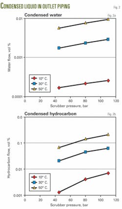
For different separator operating conditions, Fig. 2 shows the resulting condensed liquids when the temperature decreases by 1° C. It is seen that the temperature has the largest impact on the resulting amount of condensed liquids.
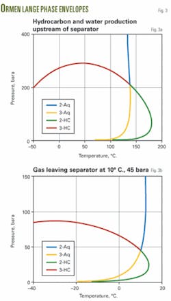
Phase envelopes (Fig. 3) indicate the fluid behavior in the separator and in the gas outlet piping at a 45 bara and 10° C. separator operating condition.
Equilibrium considerations
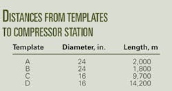
The distance from the wellheads to the compressor station varies from 1,800 to 14,200 m, and the flowlines have a 24-in. diameter from templates A and B and 16-in. from templates C and D (Fig. 4).
The residence time in the flowlines from the wellheads to the compressor station inlet is typically 3-20 min, based on a velocity of about 10 m/sec. The residence time is for the vapor phase because liquid travels slower.
The liquid phase in these flowlines mainly will flow at the pipe walls, resulting in a large contact area between the gas phase and the liquid phase.
Because the pipe length from the wellheads to the subsea compressor station is long (Table 1), it is reasonable to assume that the fluid is close to thermodynamic equilibrium with regard to phase compositions when it reaches the compressor station.
This means that one can consider the multiphase fluid entering the separator at the subsea compressor station as an equilibrium mixture. The gas phase leaving the separator will be at the dewpoint for both hydrocarbon liquid and water. The liquid phases leaving the separator will be at their boiling points.
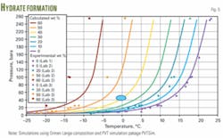
Fig. 5 shows the calculated hydrate formation curves for the Ormen Lange fluid system. The curves indicate that the Ormen Lange well fluids at a 45 bar pressure are fully inhibited with 40 wt % MEG in the aqueous phase.
MEG flowing conditions
The study assumed MEG (90 wt % MEG, 10 wt % water) being injected at the wellheads with a 1,500 cu m/day maximum capacity. The MEG concentration decreases as more water condenses from the gas phase, and when the fluid reaches land, the MEG concentration still will be 60 wt %.
The MEG concentration in the separator will be between 60 and 90 wt %. A calculation based on a maximum lean 1,500 cu m/day MEG flow rate, a 455 cu m/day water flow rate from the reservoir, and a 600 kg/sec production flow rate gives a 70 wt % MEG concentration in the MEG/water system when the separator operates at 45 bara and 10° C.
Carry over
The computer program PVTSim,11 can calculate the amount of condensed liquids in the gas outlet piping from the separator. The calculation assumes that the gas-liquid mixture in the separator is at thermal equilibrium and that the gas phase leaving the separator is at the dewpoint with respect to both water and hydrocarbons.
The temperature and pressure decrease as the gas stream flows towards the compressor inlet. With a surrounding temperature of 1° C., the calculations show that the steady-state normal operating temperature at the compressor gas inlet will not be more than 1° below the separator temperature.
The calculations show that the minimum steady state wall temperature is 9° C. The liquid will condense at the wall, but only a part of the gas will be in contact with the wall and temporarily be cooled down to a temperature below the average bulk value. The condensed liquid may therefore be somewhat greater than the calculated bulk temperature level would indicate.
The study made flash calculations with PVTSim at a 45 bara constant pressure and different temperatures on a gas mixture taken from a separator operating at 45 bara and 10° C. This condition was selected for the calculation case since the amount of condensed liquid is greatest at the lower pressure, and the 10° C. temperature is the normal operating condition.
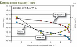
Fig. 6 shows that the condensed water cut is generally lower than 10%, and small amounts of liquid condense when the temperature decreases below 10° C.
The amount of condensed liquid at 9° C. is about 10 times less than the amount of condensed liquid at 1° C.; however, only the condensed water dilutes the MEG.
The specified separator efficiency (liquid carry over) is 0.013 cu m/million standard cu m,12 and this represents a 99.993% volumetric efficiency at the 45 bara and 10° C. operating condition. This efficiency value is high, and if the separator efficiency is lower, then even more MEG will flow through the gas outlet.
The maximum design flow rate for the subsea compressor station is 70 million standard cu m/day, which corresponds to a total mass flow rate of about 600 kg/sec. The specified 0.013 cu m/million standard cu m separator efficiency indicates that the liquid carry over will be about 38 l./hr in total (not per train).
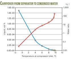
Fig. 7 shows the liquid volume% in the gas outlet piping and the volumetric ratio of water from separator to condensed water. The figure indicates that the water/MEG mixture from the separator is much greater than the condensed water for normal operating conditions.
Calculations with PVTSim on a separator operating condition of 45 bara and 10° C., show that the condensed liquid at a temperature of 9° C. is 4.5 l./hr. The volumetric ratio of water from the separator to condensed water is in this case 37.
The liquid carry over, containing about 70 wt % MEG is, therefore, only slightly diluted by the condensing water. As an example, in 37 l. of water (about 37 kg of water), the amount of MEG is 25.9 kg (corresponding to 70 wt %). Adding 1 l. or 1 kg of water reduces the MEG concentration to 68 wt %. Hence, the fluid system remains inhibited.
Other results
Other results from this study are:
- The liquid carry over from the separator contains 60-90 wt % MEG, depending on operating pressure and temperature.
- The condensed liquids in the gas outlet have a low water cut; less than 2% down to a temperature of 3° C.
- The condensed water in the gas outlet dilutes the MEG/water mixture in the carry over from the separator, but the dilution is small at normal operating conditions.
- If the liquid carry over is larger than 0.013 cu m/million standard cu m, then this is beneficial from an inhibition point of view.
- It is recommended to measure the separator efficiency and to test the hydrate remediation system such as MEG flushing at Nyhamna over a wide range of operating conditions.
- It is further recommended that to ensure a successful pilot test at Nyhamna with respect to the hydrate strategy, the test program should be planned carefully with quality input from hydrate and flow-assurance specialists.
References
- FactsThe Norwegian petroleum sector 2007, Ministry of Petroleum and Energy, www.petrofacts.no.
- Wilson, A., et al., “Ormen LangeFlow Assurance challenges,” Paper No. OTC 16555, OTC, Houston, May 3-6, 2004.
- Fantoft, R., “Subsea compressionchallenges and solutions,” Paper No. OTC 17399, OTC, Houston, May 2-5, 2005.
- Bjerkreim, B., “Subsea gas compressionA future option,” Paper No. OTC 16561, OTC, Houston, May 3-6, 2004.
- Bjerkreim, B., et al., “Ormen Lange Subsea Compression Pilot,” Paper No. OTC 18969. OTC, Apr. 30-May 3, 2007.
- Sloan, E.D., Clathrate Hydrates of Natural Gases, Editor H. Heinemann, Marcel Dekker Inc., New York and Basel, 1990.
- Peysson, Y., et al., “Flow of Hydrates Dispersed in Production Lines,” Paper No. SPE 84044, SPE ATCE, Denver, Oct. 5-8, 2003.
- Dorstewitz, F., and D. Mewes, “Hydrate formation in pipelines,” 5th International Offshore and Polar Engineering Conference, The Hague, June 11-16, 1995.
- Hegg, H.C.A., et al., “Multiphase Transport with Hydrate Formation,” Deep Offshore Technology, Houston, Oct. 10-12, 2007.
- Robøle, B., et al., “The Norsk Hydro Multiphase Flow Loop. A high Pressure Flow Loop for Real Three-Phase Hydrocarbon Systems,” Flow Measurement and Instrumentation, 2006.
- PVTSim, Version 15, Calsep AS, Denmark, www.calsep.com.
- NORSOK, Process systems, P-100 Rev. 2, Norwegian Technology Centre, November 2001.
Based on a presentation to the Deep Offshore Technology International Conference & Exhibition, Houston, Feb. 12-14, 2008.
The authors
Geir Elseth is a researcher at StatoilHydro’s Research Centre in Porsgrunn, Norway. He has worked with experimental research within the field of flow assurance for 7 years in Hydro ASA but is currently working with inflow control for increased oil recovery. Elseth holds a PhD in petroleum technology from the Norwegian University of Science and Technology.
Reidar Barfod Schüller is professor at the Norwegian University of Life Sciences. He has worked with the research division of Norske Veritas and has industrial research experience from Norsk Hydro ASA and StatoilHydro AS, especially in experimental multiphase flow with special focus on real hydrocarbon-water systems. Schüller holds a PhD in mechanical engineering from Heriot-Watt University, Edinburgh, UK.


